Capping mechanism of full-automatic capping machine

A capping machine, fully automatic technology, applied in the direction of packaging, etc., can solve the problems of reducing automation efficiency, wasting air source, and low production efficiency

Active Publication Date: 2021-05-18
JIANGSU TOM PACKAGING MACHINERY
View PDF8 Cites 2 Cited by
  • Summary
  • Abstract
  • Description
  • Claims
  • Application Information

AI Technical Summary

Problems solved by technology

[0002] At present, the capping machines in the industry are not stable enough when running at high speed, resulting in low production efficiency; and the capping head of the capping machine is in a state of constant ventilation, which wastes the air source when the cap is not needed; in addition, once a special cap type appears , like the mosquito coil liquid core rod, when it is broken in the capping head, it will cause the cap to not be sucked normally next time, and the capping head needs to be removed manually to take out the broken packaging material, which greatly reduces the automation efficiency

Method used


Image

  • Capping mechanism of full-automatic capping machine
  • Capping mechanism of full-automatic capping machine
  • Capping mechanism of full-automatic capping machine

Examples


Embodiment

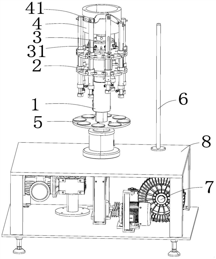
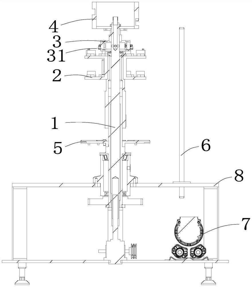
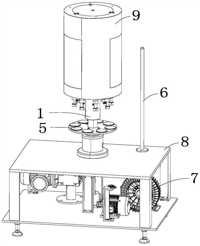
[0035] Embodiment: a capping mechanism of a fully automatic capping machine, as attached figure 1 with 2 As shown, the capping mechanism in this embodiment includes a main shaft 1, and the main shaft 1 is sequentially provided with a cam 4, a vacuum control device, a lifting part 2 and a suction cap part 5 from top to bottom; On the frame 8, the mounting frame 8 includes a mounting surface at the top, a mounting cavity at the middle and mounting legs at the bottom, wherein the cam 4, the vacuum control device, the lifting part 2 and the suction cover part 5 are all located above the mounting surface, The power device that drives the main shaft 1 to rotate is located in the installation cavity; image 3 As shown, the main shaft 1 in this embodiment is provided with a protective casing 9, and the casing 9 covers and protects the cam 4 on the main shaft 1, the vacuum control device, and the lifting part 2, so as to improve the cleanliness of the equipment.

[0036] as attached ...


PUM


Abstract

The invention discloses a capping mechanism of a full-automatic capping machine. The capping mechanism comprises a main shaft, wherein the main shaft is sequentially provided with a cam, a vacuum control device, a lifting portion and a cap sucking portion from top to bottom; a cam groove is formed in the side wall of the cam, the top of the lifting portion rotates along the cam groove in the cam, a capping head is arranged at the bottom of the lifting portion, and the lifting portion rotates along the cam groove and the vacuum control device is used for realizing cap sucking and pressing of the capping head on the cap sucking portion; the vacuum control device comprises a vacuum receiving disc, a vacuum rotating disc and a vacuum device; an annular gap is reserved between the vacuum receiving disc and the vacuum rotating disc, and the annular gap is divided into a ventilation area and an air-free area through a partition rib; and when the lifting portion is used for sucking and pressing caps, a corresponding second air joint on the vacuum rotating disc is rotated to the ventilation area, and when the lifting portion completes capping, the corresponding second air joint on the vacuum receiving disc is rotated to the air-free area. The capping mechanism is high in automation degree and high in safety coefficient, and the labor cost is saved.

Description

technical field [0001] The invention belongs to the field of automatic packaging machinery, and in particular relates to a capping mechanism of a fully automatic capping machine. Background technique [0002] At present, the capping machines in the industry are not stable enough when running at high speed, resulting in low production efficiency; and the capping head of the capping machine is in a state of constant ventilation, which wastes the air source when the cap is not needed; in addition, once a special cap type appears , Like the mosquito coil liquid mandrel, when it is broken in the capping head, it will cause the next time the cap cannot be sucked normally, and the capping head needs to be removed manually to take out the broken packaging material, which greatly reduces the automation efficiency. Contents of the invention [0003] Purpose of the invention: The purpose of the invention is to provide a capping mechanism of a fully automatic capping machine for the d...

Claims


Application Information

Patent Timeline
IPC IPC(8): B65B7/28
CPCB65B7/2807B65B7/2842
Inventor 李争阳刘洋吴云晖孙绪清张太诚
Owner JIANGSU TOM PACKAGING MACHINERY
Why Eureka
Try Eureka