Automatic tube breaking device for microscopic tube

A workbench and cavity technology, applied in glass cutting devices, manufacturing tools, glass manufacturing equipment, etc., can solve the problem of easy adhesion of microtubes/oviducts to fine glass particles, movement of microtubes/oviducts, etc. question

Active Publication Date: 2021-05-18
山东美毅生物技术有限公司
View PDF4 Cites 0 Cited by
  • Summary
  • Abstract
  • Description
  • Claims
  • Application Information

AI Technical Summary

Problems solved by technology

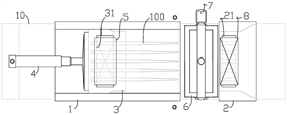
[0004] Aiming at the problem of poor consistency of broken tubes existing in the process of cutting segmented tubes, the present invention provides a microtube automatic tube breaking device, which improves microtubes, such as the clamping structure in the process of cutting oviducts , to solve the problem of the movement of microtubes / striped oviducts in the process of breaking the tubes, and to better ensure that the length of the microtubes / striped oviducts obtained by cutting has good consistency
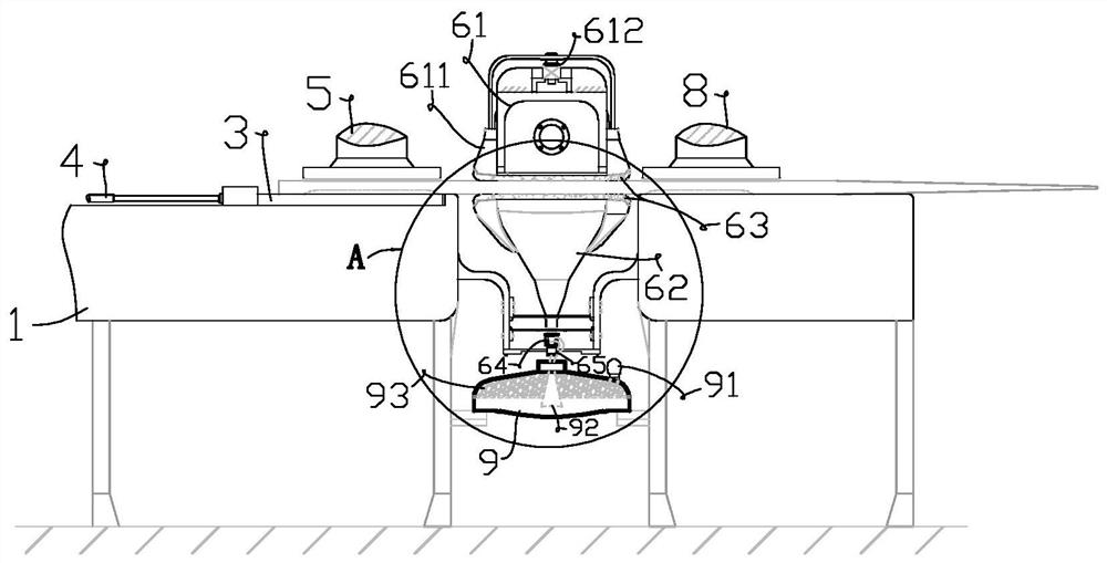
In addition, a closed space capable of forming a negative pressure flow is set in the cutting device to solve the problem that fine glass particles are easily attached to the inner wall of the microtube / oviduct after the tube is broken, which helps to ensure the microscopic tube after the tube is broken. Tubes / strips have good cleanliness

Method used


Image

  • Automatic tube breaking device for microscopic tube
  • Automatic tube breaking device for microscopic tube
  • Automatic tube breaking device for microscopic tube

Examples


Embodiment Construction

[0035] The structures, proportions, sizes, etc. shown in the accompanying drawings of the description are only used to match the content disclosed in the description, for those who are familiar with the technology to understand and read, and are not used to limit the conditions for the implementation of the present invention, so there is no Technically, any modification of structure, change of proportional relationship or adjustment of size shall still fall within the scope of the technical content disclosed in the present invention without affecting the functions and objectives of the present invention. within the range that can be covered. At the same time, terms such as "upper", "lower", "front", "rear", and "middle" quoted in this specification are only for the convenience of description, and are not used to limit the scope of the present invention. , the change or adjustment of its relative relationship, without substantive changes in the technical content, should also be...


PUM


Abstract

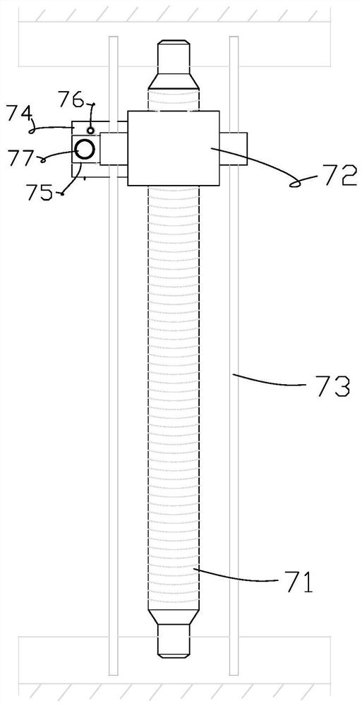
The invention relates to an automatic tube breaking device for a microscopic tube. The automatic tube breaking device comprises a pair of workbenches, a pushing mechanism, a cutter, a sliding table arranged on one workbench, a pressing block mechanism a arranged over the sliding table and a pressing block mechanism b arranged over the other workbench. The upper end face of the sliding table is provided with a plurality of protruding blocks A which are arranged at intervals, and the other workbench is provided with a plurality of protruding blocks a which are arranged at intervals. The microscopic tube can be clamped between the two adjacent protruding blocks A. The pressing block mechanism a is pressed on the microscopic tube. The pushing mechanism can push the sliding table to move towards the other workbench, and the block pressing mechanism a can move synchronously with the sliding table during the period. The tip end of the microscopic tube can gradually pass through the space between the adjacent bumps a. The middle part of the microscopic tube can be clamped between the two bumps a so that the pressing block mechanism b can be pressed on the microscopic tube. By improving the clamping structure in the microscopic tube cutting process, the problem that the microscopic tube moves in the tube breaking process is solved, and it is guaranteed that the lengths of the cut microscopic tubes are good in consistency.

Description

technical field [0001] The invention relates to the field of cutting microtubes by using a cutting sheet, in particular to a cutting device in the process (step) of breaking microtubes (such as oviducts) and the like. Background technique [0002] Glass microtubes or glass microneedles, such as egg stripping tubes (or microscopic egg stripping tubes, egg stripping needles), etc. generally need to be finished by pulling tubes, breaking tubes, polishing and other process steps to obtain finished products. The blank is mostly a glass tube with an inner diameter of 1.5mm. The cutting method adopted in the current production process of glass microtubes is mainly to cut a piece of tube (needle) or break the tube (needle) on a calciner. Taking the oviduct stripping as an example, the method of cutting into pieces mainly has the problem of poor consistency of the length of the finished oviduct stripping. The broken tube (needle) of the calciner has the problems that the cutting pr...

Claims


Application Information

Patent Timeline
Patent Type & Authority Applications(China)
IPC IPC(8): C03B33/06
CPCC03B33/06Y02P40/57
Inventor 陈春晓陈蕾任潇宇
Owner 山东美毅生物技术有限公司
Why Eureka
Try Eureka