
Fabricated profile steel confined concrete shear wall structure

A technology for confining concrete and shear walls, applied to walls, building components, building structures, etc., can solve problems such as troubles for construction personnel, poor seismic performance, and difficult positioning of steel bars

Inactive Publication Date: 2021-05-18
ZHENGZHOU UNIVERSITY OF AERONAUTICS
View PDF0 Cites 0 Cited by
  • Summary
  • Abstract
  • Description
  • Claims
  • Application Information

AI Technical Summary

Problems solved by technology

These connection methods require a large number of steel bars to be connected, which not only increases the cost of the structure, but also causes great trouble to the construction workers due to the difficulty in positioning the steel bars during the installation process, and the seismic performance is not good.

Method used


Image

  • Fabricated profile steel confined concrete shear wall structure
  • Fabricated profile steel confined concrete shear wall structure
  • Fabricated profile steel confined concrete shear wall structure

Examples


Embodiment 1

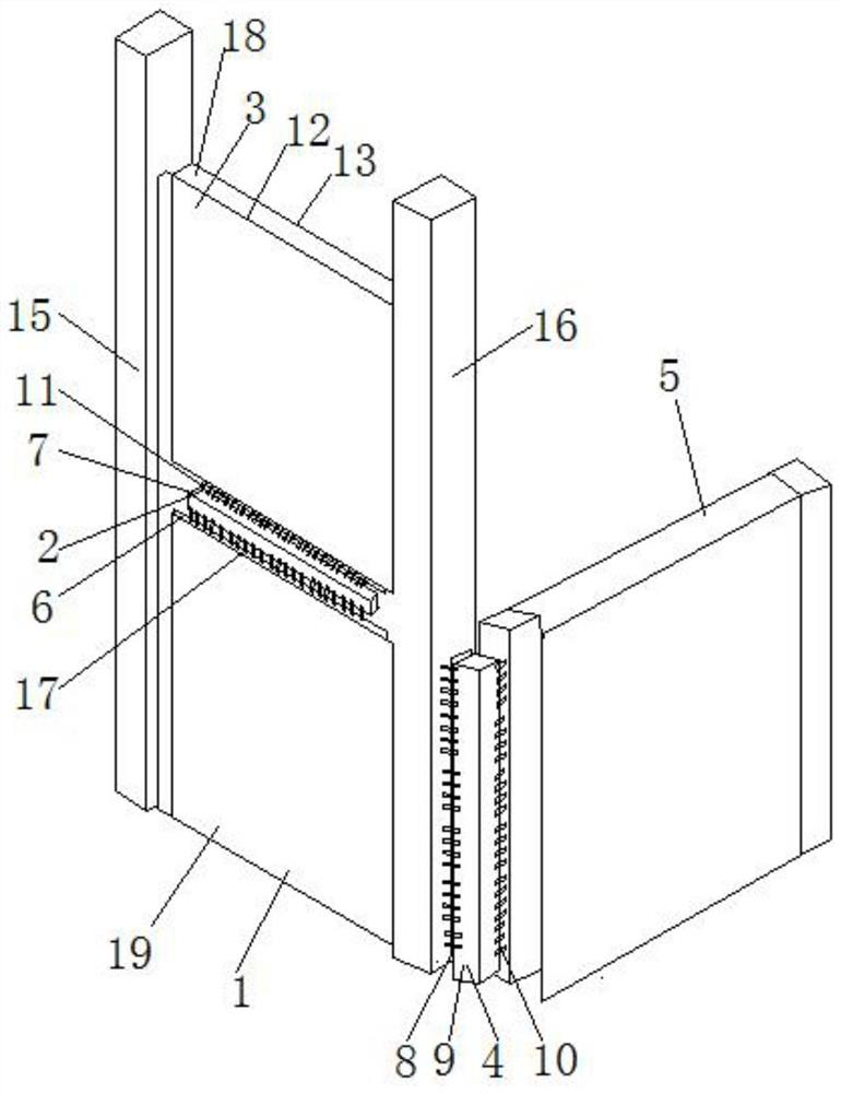
[0027] A prefabricated steel-confined concrete shear wall structure, such as figure 1 As shown, it includes: a lower shear wall unit 1, the upper side of which is connected with an upper shear wall unit 3, and the side of the lower shear wall unit 1 is connected with a side shear wall unit 5; the first connector 2 is connected to the lower shear wall Between the force wall unit 1 and the upper shear wall unit 3, the first connector 2 includes the first H-shaped steel 6 respectively connected to the lower shear wall unit 1 and the upper shear wall unit 3, and the lower shear wall unit 1 The flange on the first H-shaped steel 6 extends upward, the flange on the first H-shaped steel 6 on the upper shear wall unit 3 extends downward, and a first square steel pipe is arranged between the two first H-shaped steel 6 7. Between the flanges of the two first H-shaped steels 6 and the first square steel pipe 7, a plurality of first reinforcing ribs 11 are respectively arranged, and the p...

Embodiment 2

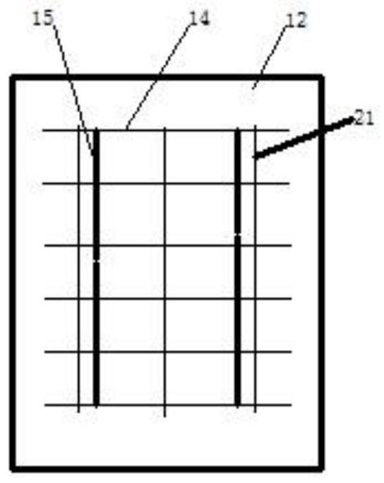
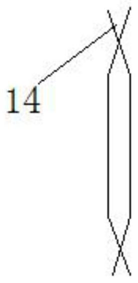
[0031] Further, on the basis of embodiment 1, such as Figure 2-3As shown, the lower shear wall unit 1, the upper shear wall unit 3 and the side shear wall unit 5 all include vertical and face-to-face first steel plates 12 and second steel plates 13 respectively, and the first steel plates 12 and the second steel plates Between 13, there are multiple layers of corrugated reinforced bars 14, each layer including two corrugated reinforced bars 14, the waveform positions of the two corrugated reinforced bars 14 intersect each other and form two nodes, and two adjacent layers of corrugated reinforced bars The nodes formed by 14 are connected by polystyrene boards 15 arranged vertically, and the periphery of the floor frame formed between the multi-layer corrugated reinforced steel bars 14 is also provided with a plurality of ring-type connecting beam stirrups 21 in parallel and equidistantly. The connecting beam stirrup 21 is vertically arranged with the corrugated reinforced stee...


PUM


Abstract

The invention discloses a fabricated profile steel confined concrete shear wall structure. A lower shear wall unit is connected with an upper shear wall unit through a first connecting piece, and the lower shear wall unit is connected with a side shear wall unit through a second connecting piece. The lower shear wall unit, the upper shear wall unit and the side shear wall unit can be pre-machined in a part machining factory, the pre-machined lower shear wall unit, the pre-machined upper shear wall unit and the pre-machined side shear wall unit are transported to a mounting place and then assembled through the first connecting piece and the second connecting piece, and then concrete is poured to the fabricated shear wall unit. Compared with a traditional cast-in-place building structure construction method, on-site hoisting and combination are convenient, the operation time is shortened, on-site labor force is reduced, and the assembly efficiency is improved.

Description

technical field [0001] The invention belongs to the technical field of building wallboards, and in particular relates to an assembled steel-constrained concrete shear wall structure. Background technique [0002] For the "assembled integral concrete shear wall structure" that is currently emerging in China, the vertical connection of the wall reinforcement mostly adopts the "sleeve connection" or "constrained slurry anchor connection" method. These connecting methods all need to connect a large number of steel bars, which not only increases the structural cost, but also causes great trouble to the construction workers due to the difficulty in positioning the steel bars during the installation process, and the seismic performance is not good. Contents of the invention [0003] The object of the present invention is to provide an assembled steel-confined concrete shear wall structure, and provide a steel-confined concrete shear wall structure that is easy to install and has ...

Claims


Application Information

Patent Timeline
Patent Type & Authority Applications(China)
IPC IPC(8): E04B2/56E04B2/60E04B2/00
CPCE04B2/00E04B2/56E04B2/60
Inventor 李晓虎李广慧栗蕾温翔科周志阳
Owner ZHENGZHOU UNIVERSITY OF AERONAUTICS
Learn More