Resistance test circuit and system

A resistance test and circuit technology, applied in the direction of measuring resistance/reactance/impedance, measuring devices, measuring electrical variables, etc., can solve problems such as poor test reliability

Pending Publication Date: 2021-05-18
广电计量检测(成都)有限公司
View PDF0 Cites 0 Cited by
  • Summary
  • Abstract
  • Description
  • Claims
  • Application Information

AI Technical Summary

Problems solved by technology

[0004] Based on this, it is necessary to provide a resistance test circuit and system for the problem of poor test reliability of the traditional resistance test scheme

Method used


Image

  • Resistance test circuit and system
  • Resistance test circuit and system
  • Resistance test circuit and system

Examples


Embodiment Construction

[0027] In order to facilitate the understanding of the present application, the present application will be described more fully below with reference to the relevant drawings. Preferred embodiments of the application are shown in the accompanying drawings. However, the present application can be embodied in many different forms and is not limited to the embodiments described herein. On the contrary, the purpose of providing these embodiments is to make the understanding of the disclosure of the application more thorough and comprehensive.

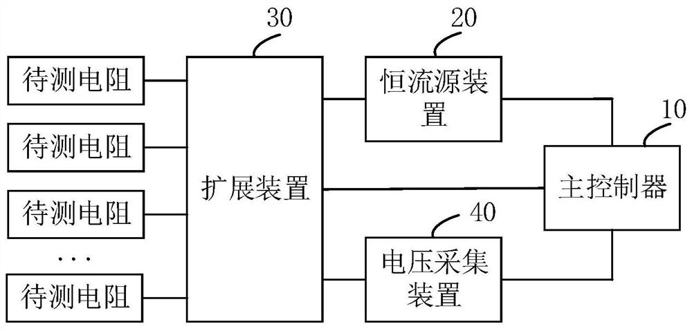
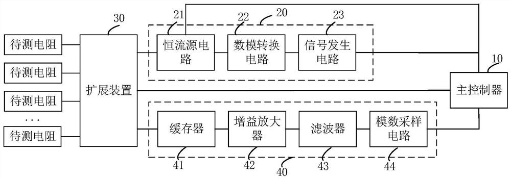
[0028] see figure 1 , a resistance testing circuit, comprising: a constant current source device 20, an expansion device 30, a voltage acquisition device 40 and a main controller 10, the constant current source device 20, the expansion device 30 and the voltage acquisition device 40 are respectively connected to the main controller 10, The constant current source device 20 and the voltage acquisition device 40 are respectively connected t...


PUM


Abstract

The invention relates to a resistance test circuit and system, and during resistance test, a plurality of to-be-tested resistors are simultaneously connected by using an expansion device, and the to-be-tested resistors are sequentially connected in series through an internal connection cable of the expansion device. Under the control of the main controller, the constant current source device generates a current signal and transmits the current signal to the expansion device, and then the current signal sequentially flows into each resistor to be measured through the expansion device. Finally, the expansion device connects the two ends of each resistor to be tested to a voltage acquisition device through a test cable, voltage signals flowing through the resistors are acquired through the voltage acquisition device, and the resistance values of the resistors to be tested can be obtained by analyzing through the ohm theorem. According to the scheme, a plurality of to-be-tested resistors can be accessed at the same time for testing by utilizing the expansion device, and current signals flowing into the to-be-tested resistors are consistent, so that the test conditions of the to-be-tested resistors are consistent while the multi-path resistor test is realized, and the test reliability is relatively high.

Description

technical field [0001] The present application relates to the technical field of reliability testing, in particular to a resistance testing circuit and system. Background technique [0002] With the development of the field of reliability and environmental testing, and especially the use of more and more integrated circuits in the car by major car manufacturers, the indicators of various performance tests are required to be very accurate, and various parameters need to be accurately monitored and recorded. , such as the resistance measurement of tiny resistors. [0003] However, the existing resistance tester generally has only one channel, and when multiple resistances need to be tested, multiple resistance testers need to be used, and the test operation is inconvenient. And due to the use of different resistance testers, it is easy to cause differences in the test conditions of each resistance, and it is difficult to guarantee the consistency of multi-path resistance test...

Claims


Application Information

Patent Timeline
IPC IPC(8): G01R27/08
CPCG01R27/08
Inventor 明志茂刘蓓辉潘健宁陈旭波周明霞
Owner 广电计量检测(成都)有限公司
Why Eureka
Try Eureka