
Central electronic hysteroscope, lens mounting end cover thereof, and uterine cavity moving operation platform

A technology of electronic palace and installation end, applied in the medical field, can solve the problems of patient injury, limit the range of activities, affect the operator's field of vision, etc., and achieve the effect of easy operation and reduced overall size

Pending Publication Date: 2021-05-25
SHANGHAI YODO MEDICAL TECH
View PDF5 Cites 4 Cited by
  • Summary
  • Abstract
  • Description
  • Claims
  • Application Information

AI Technical Summary

Problems solved by technology

The traditional hysteroscope has a large diameter of the mirror body, which often leads to unavoidable contact with the patient's body when entering the patient's body for examination, causing unnecessary harm to the patient
In addition, the larger diameter of the mirror body also limits the range of motion of traditional hysteroscopy to a certain extent, and affects the effect of hysteroscopy to a certain extent.
[0005] On the other hand, due to limitations in imaging quality, lens manufacturing technology, and manufacturing costs, it is very difficult to further reduce the size of the end portion of the traditional disposable electronic hysteroscope with the lens body, which has become a constraint for the further development of disposable electronic hysteroscopes. key factors for development
[0006] In addition, the lens of the traditional disposable electronic hysteroscope is parallel to the channel of the working tube. During the operation, the working instruments in the working channel cannot be well located in the center of the lens field of view, which affects the operator's field of vision and is not convenient for the operator. operate

Method used


Image

  • Central electronic hysteroscope, lens mounting end cover thereof, and uterine cavity moving operation platform
  • Central electronic hysteroscope, lens mounting end cover thereof, and uterine cavity moving operation platform
  • Central electronic hysteroscope, lens mounting end cover thereof, and uterine cavity moving operation platform

Examples


Embodiment 1

[0076] Reference manual attached Figure 1 to Figure 7 , the central type electronic hysteroscope provided by the present invention is described, the lens end of the central type electronic hysteroscope has a smaller size, so that the use of the central type electronic hysteroscope can be facilitated.

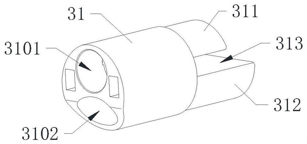
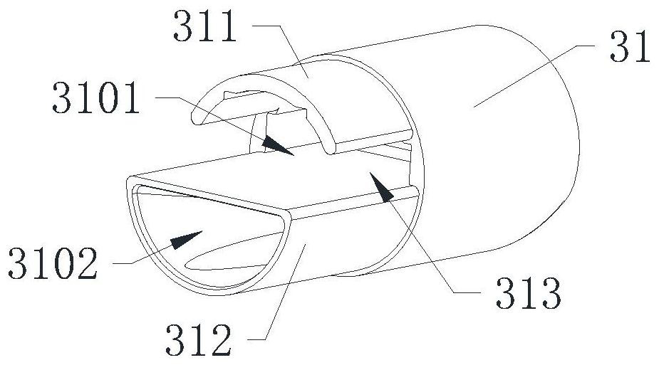
[0077] Reference manual attached figure 2 , image 3 as well as Figure 7 Specifically, the central electronic hysteroscope includes an operating handle 1, a tube body 2 and a lens mounting end cap 3, the tube body 2 is mounted on the operating handle 1, and the lens mounting end cap 3 is mounted on the The end of the tube body 2 away from the operating handle 1 .

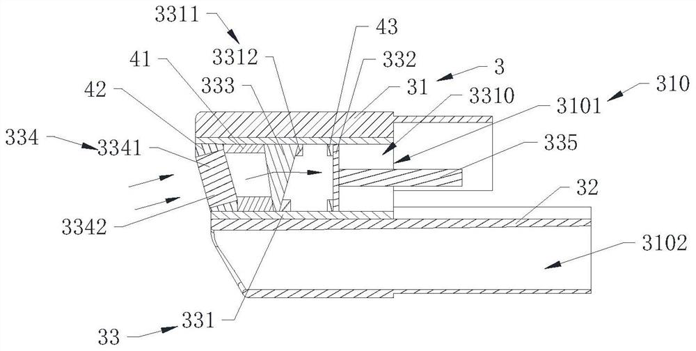
[0078] Reference manual attached figure 1 Further, the lens mounting end cap 3 includes an end cap housing 31 , an end cap partition 32 and a lens module 33 . The end cover housing 31 has an end cover cavity 310, the end cover partition 32 is installed in the end cover cavity 310, and divides the end cover cav...

Embodiment 2

[0125] Reference manual attached Figure 8 and Figure 9 The lens mounting end cap 3a of the second preferred embodiment of the lens mounting end cap provided by the present invention is described, and the structure of the lens mounting end cap 3a of the second preferred embodiment is substantially the same as that of the above preferred embodiment, The difference is that the photosensitive chip and the lens are respectively installed in the housing of the end cap to reduce the overall size of the end cap where the lens is installed.

[0126] Specifically, the lens mounting end cap 3a includes an end cap housing 31a, an end cap partition 32a, a photosensitive chip 332a and a lens assembly 334a, the end cap housing 31a has an end cap cavity 310a, and the end cap partition 32a divides the end cap cavity 310a into an upper end cap cavity 3101a and a lower end cap cavity 3102a. The photosensitive chip 332a and the lens assembly 334a are installed in the upper end cap cavity 3101...

Embodiment 3

[0155] Reference manual attached Figure 10 to Figure 15 , the third preferred embodiment of the lens mounting end cap of the central electronic hysteroscope provided by the present invention is described, the lens mounting end cap of the central electronic hysteroscope in the third preferred embodiment is the same as the above-mentioned first The difference between the first preferred embodiment and the second preferred embodiment is that the photosensitive chip and the lens assembly are independently installed on the end cover housing.

[0156] Specifically, the lens mounting end cap of the central electronic hysteroscope provided in the third preferred embodiment includes an end cap housing 31b, an end cap partition 32b, a lens assembly 33b, a photosensitive chip 34b and a prism 35b. The end cover housing 31b has an end cover cavity 310b; the end cover partition 32b is installed in the end cover cavity 310b, and divides the end cover cavity 310b into an upper end cover cavi...


PUM


Abstract

The invention discloses a central electronic hysteroscope, a lens mounting end cover thereof, and a uterine cavity moving operation platform. The lens mounting end cover of the central electronic hysteroscope comprises an end cover shell which is provided with an end cover cavity; an end cover partition plate which is mounted in the end cover cavity and divides the end cover cavity into an upper end cover cavity and a lower end cover cavity; a lens assembly which is obliquely mounted in the upper end cover cavity relative to the end cover shell and faces the lower end cover cavity; a photosensitive chip which is mounted in the upper end cover cavity; a prism which is installed in the upper end cover cavity, and the prism is located between the lens assembly and the photosensitive chip, wherein light passing through the lens assembly is refracted by the prism and then irradiates the photosensitive chip. The lens assembly of the lens mounting end cover is obliquely arranged and faces the lower end cover cavity through which the working apparatus passes, so that the working apparatus can be located in the view center of the lens assembly in the use process, and operation is convenient.

Description

technical field [0001] The invention relates to the medical field, and further relates to a central electronic hysteroscope, a lens mounting end cap and a mobile operating platform for the uterine cavity. Background technique [0002] Hysteroscopy is a new, minimally invasive gynecological diagnosis and treatment technology. It is a light source endoscope used for inspection and treatment of the uterine cavity. The magnification effect, with the advantages of intuition and accuracy, has become the first choice of inspection equipment for gynecological hemorrhagic diseases and intrauterine lesions. [0003] In recent years, with the continuous development of technology, disposable electronic hysteroscopes have developed rapidly. Compared with non-disposable electronic hysteroscopes, disposable electronic hysteroscopes are clean and hygienic, do not require multiple disinfections, and have excellent lens imaging quality. Guarantee and other advantages have been widely used in...

Claims


Application Information

Patent Timeline
IPC IPC(8): A61B1/303A61B1/04
CPCA61B1/303A61B1/04A61B1/00163A61B1/00137
Inventor 王臣峰杨翔郝进争
Owner SHANGHAI YODO MEDICAL TECH
Learn More