
Connecting mechanism and medical instrument

A connection mechanism and docking part technology, applied in medical science, surgery, surgical fixation nails, etc., can solve problems such as damage to component life, docking difficulties, switching parts and docking parts cannot be meshed, etc., to achieve no damage to component life and reasonable structure Effect

Pending Publication Date: 2021-05-25
SUZHOU YINGTUKANG MEDICAL TECH CO LTD
View PDF0 Cites 0 Cited by
  • Summary
  • Abstract
  • Description
  • Claims
  • Application Information

AI Technical Summary

Problems solved by technology

The closing drive assembly and the firing drive assembly of the electric circular stapler share a power input device, and it is necessary to selectively connect the power input device with the closing drive assembly and the firing drive assembly during work. The existing technology to realize this function is to use The connection mechanism connects the input shaft of the power input device with the working shaft of the closing drive assembly or the firing drive assembly. The connection mechanism includes two docking parts connected with the input shaft and the working shaft and a switching piece engaged with the two docking parts, but the connection There are problems when the switching part of the mechanism is meshed with the docking part. The switching part cannot mesh with the docking part. It needs to rotate the input shaft or working shaft connected to the docking part to engage. Even if the docking is difficult, it will also damage the life of the parts.
In addition, there is also the problem that the connection mechanism cannot maintain the corresponding connection position well, so that the doctor's operation cannot be completed smoothly, and even the operation fails.

Method used


Image

  • Connecting mechanism and medical instrument
  • Connecting mechanism and medical instrument
  • Connecting mechanism and medical instrument

Examples


Embodiment Construction

[0022] The specific implementation manners of the present invention will be further described in detail below in conjunction with the accompanying drawings and embodiments. The following examples are used to illustrate the present invention, but are not intended to limit the scope of the present invention.

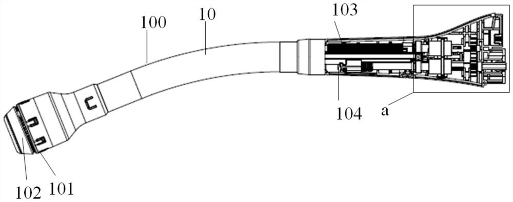
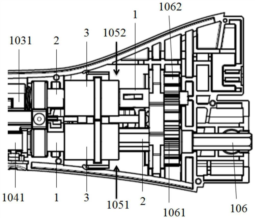
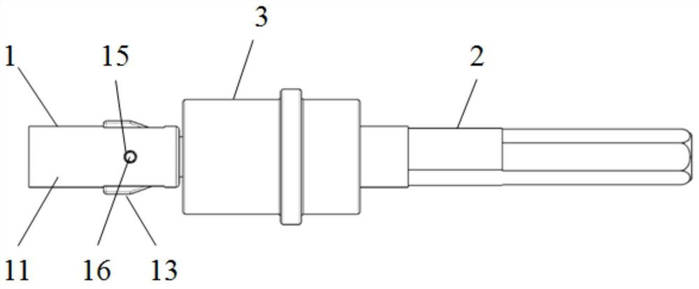
[0023] The medical device shown in one embodiment of the present invention includes a working head and an end effector on the working head, and the working head is provided with a power input shaft, an execution drive shaft and connecting the power input shaft and the execution drive shaft The connecting mechanism, the end effector is connected with the driving shaft. For details, see figure 1 with figure 2 In this embodiment, the medical device takes an electronically controlled circular stapler 10 as an example, and the circular stapler 10 includes a housing 100, a power input device (not shown) that provides power, and is arranged on the housing 100. The staple cart...


PUM


Abstract

The invention relates to a connecting mechanism, which comprises a first butt joint part, a second butt joint part parallel to the first butt joint part, and a switching piece arranged between the first butt joint part and the second butt joint part in a sleeving mode. One end of the switching piece is internally meshed with the second butt joint part, the other end of the switching piece is in butt joint with the first butt joint part, and the switching piece can move on the second butt joint part relative to the first butt joint part so that the switching piece can be partially arranged on the first butt joint part in a sleeving mode or be separated from the first butt joint part. A butt joint cavity with a round section and a plurality of butt joint blocks formed by extending inwards from the side wall of the butt joint cavity are formed in the switching piece, a butt joint groove is formed between every two adjacent butt joint blocks, an inserting piece used for being contained in at least part of the butt joint grooves is formed on the first butt joint part, and when the switching piece is arranged on the first butt joint part in a sleeving mode, and the inserting piece can be extruded by the butt joint block to move in the radial direction of the first butt joint part. The connecting mechanism can be used for smoothly and reliably connecting the two butt joint parts without obstacles in any state, and the service life of parts is not damaged.

Description

technical field [0001] The invention relates to a connection mechanism and a medical device. Background technique [0002] In general surgery, circular staplers are often used to cut and close tissues. In the existing electric circular stapler, doctors need to connect the power input device with the closing drive assembly to close the proximal and distal tissues, and connect the power input device with the firing drive assembly under reasonable tissue compression conditions to complete the anastomosis. The closing drive assembly and the firing drive assembly of the electric circular stapler share a power input device, and it is necessary to selectively connect the power input device with the closing drive assembly and the firing drive assembly during work. The existing technology to realize this function is to use The connection mechanism connects the input shaft of the power input device with the working shaft of the closing drive assembly or the firing drive assembly. The...

Claims


Application Information

Patent Timeline
Patent Type & Authority Applications(China)
IPC IPC(8): A61B17/115
CPCA61B17/115A61B2017/00017
Inventor 姜飞张翚刘殿臣杜运峰
Owner SUZHOU YINGTUKANG MEDICAL TECH CO LTD
Learn More