Supercharge Your Innovation With Domain-Expert AI Agents!

Plastic particle mixing device

A mixing device and technology of plastic particles, applied in the field of plastic processing, can solve the problems of high accumulation pressure of plastic particles, poor mixing effect, inability to mix plastic particles uniformly, etc., and achieve the effect of convenient discharging, not easy to block, and convenient and uniform mixing.

Inactive Publication Date: 2021-05-25
张钟元
View PDF0 Cites 0 Cited by
  • Summary
  • Abstract
  • Description
  • Claims
  • Application Information

AI Technical Summary

Problems solved by technology

[0005] Aiming at the deficiencies of the prior art, the present invention provides a mixing device for plastic granules, which solves the problem that the currently used mixing and agitating devices usually directly use stirring rollers to agitate the plastic granules, and cannot evenly mix the upper and lower plastic granules. The accumulation pressure of plastic particles is relatively high, the movement of plastic particles inside the mixing drum is relatively light, and the mixing effect is poor

Method used


Image

  • Plastic particle mixing device
  • Plastic particle mixing device
  • Plastic particle mixing device

Examples


Embodiment 1

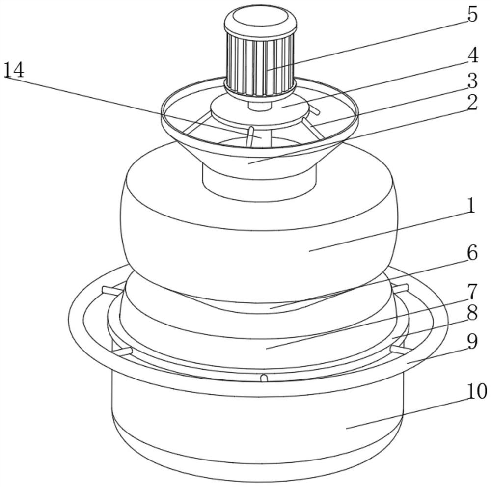
[0031] see Figure 1-3, the present invention provides a technical solution: a plastic particle mixing device, comprising a first processing box 1, the top of the first processing box 1 is provided with a feed port 2, and the top of the inner wall of the feed port 2 is fixedly connected with a bracket through a support rod 3 The plate 4 and the top of the supporting plate 4 are fixedly connected with the driving motor 5, the bottom of the first processing box 1 is connected with the second processing box 7 through the conical cylinder 6, and the outer side of the bottom of the second processing box 7 is slidingly connected with the retaining ring 8, the retaining ring 8 The outer side of the top is fixedly connected with the rotating ring 9 through the connecting rod, the outer side of the retaining ring 8 is slidably connected with the collection box 10, the side of the retaining ring 8 is provided with a long sliding hole 11, and the side of the second processing box 7 is fix...

Embodiment 2

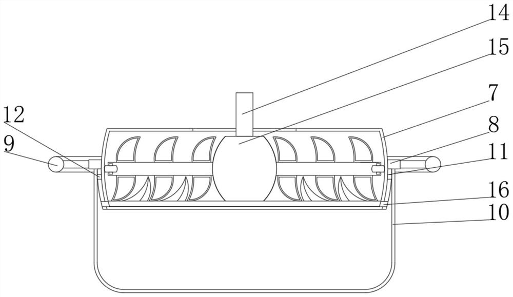
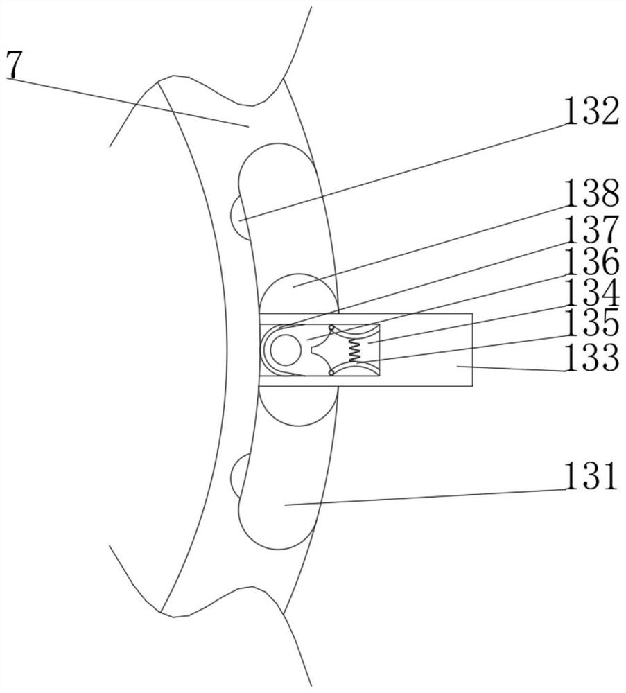
[0034] see Figure 1-5 On the basis of Embodiment 1, the present invention provides a technical solution: the stirring device 15 includes a stirring seat 151, the stirring seat 151 is provided with a movable chamber 152, and both sides of the movable chamber 152 inner wall are provided with movable holes 153, and the movable holes 153 The inner wall is slidingly connected with a stirring rod 154, and one end of the stirring rod 154 located inside the movable chamber 152 is fixedly connected with a compression magnet 155, and the end of the stirring rod 154 away from the compression magnet 155 penetrates the movable hole 153 and extends to the outside of the stirring seat 151. 154 is located at the top and bottom of one end outside the stirring seat 151 and is fixedly connected with stirring blades 156. The end of the stirring rod 154 away from the compression magnet 155 is rotatably connected with a roller 159, and both sides of the bottom of the stirring seat 151 are fixedly c...


PUM


Abstract

The invention discloses a plastic particle mixing device. The plastic particle mixing device comprises a first treatment box, a feeding opening is formed in the top of the first treatment box, a supporting plate is fixedly connected to the top of the inner wall of the feeding opening through a supporting rod, a driving motor is fixedly connected to the top of the supporting plate, the bottom of the first treatment box communicates with a second treatment box through a conical barrel, a check ring is slidably connected to the outer side of the bottom of the second treatment box, a rotating ring is fixedly connected to the outer side of the top of the check ring through a connecting rod, a collecting box is slidably connected to the outer side of the check ring, a long sliding hole is formed in the side face of the check ring, and a connecting block is fixedly connected to the portion, corresponding to the long sliding hole, of the side face of the second treatment box. The invention relates to the technical field of plastic processing. According to the plastic particle mixing device, plastic particles can move more easily, uniform mixing of the plastic particles is facilitated, discharging is more convenient, a discharging opening is not easy to be blocked, the particle mixing effect is better, and the discharging is also more convenient.

Description

technical field [0001] The invention relates to the technical field of plastic processing, in particular to a plastic particle mixing device. Background technique [0002] Plastic processing is also called plastic molding processing. It is mainly to make plastic into plastic products. In this process, multiple steps are required. First, the raw materials need to be mixed and stirred so that different types of The mixing degree of plastic particles is more uniform, thereby improving the wear resistance and firmness of plastics. [0003] However, the currently used mixing and stirring devices usually use stirring rollers to directly stir the plastic particles, which cannot evenly mix the plastic particles above and below, and due to the high accumulation pressure of the plastic particles, the movement of the plastic particles inside the mixing drum is relatively light. Mixing effect is poor. Contents of the invention [0004] (1) Solved technical problems [0005] Aiming ...

Claims


Application Information

Patent Timeline
IPC IPC(8): B29B7/16B29B7/26
CPCB29B7/16B29B7/26
Inventor 徐洪舟
Owner 张钟元
Features
  • R&D
  • Intellectual Property
  • Life Sciences
  • Materials
  • Tech Scout
  • Unparalleled Data Quality
  • Higher Quality Content
  • 60% Fewer Hallucinations
Learn More