
Automatic fixing device based on commercial vehicle unmanned transfer system

A technology for fixing devices and commodities, which is applied in the direction of goods transportation vehicles, transportation and packaging, and vehicles used for freight transportation, etc. It can solve the problems of high labor intensity of manual work, failure to realize full automation, and inability to realize automation, etc., and achieve structural Simple, small footprint, simple action effect

Pending Publication Date: 2021-05-25
JILIN UNIV
View PDF1 Cites 0 Cited by
  • Summary
  • Abstract
  • Description
  • Claims
  • Application Information

AI Technical Summary

Problems solved by technology

Disadvantages: manual work is required, automation cannot be realized, and manual work is labor-intensive in the case of batch transportation
The plane of the carrying steel plate is a mesh-shaped rectangular fixing hole. After the vehicle is driven to a suitable position, four straps are used to fix the tires of the vehicle one by one, and the straps are fixed into the mesh-like fixing holes of the plane through the grab hook. There are three fixed points, that is, it needs to be fixed at least 12 times to fix the four wheels on the vehicle. The process is very cumbersome
If the vehicle needs to be transported in a cross-border sea container, the fixing of the vehicle in the container is more cumbersome. At least four wooden fixing blocks for each wheel need to be fixed to the carrying wooden board at the bottom of the container with steel nails, and straps are added. The process is very cumbersome
At this stage, the research on automatic vehicle fixing devices has a relatively complicated structure for the device body, and most of them still require manual auxiliary intervention, and have not yet achieved full automation.

Method used


Image

  • Automatic fixing device based on commercial vehicle unmanned transfer system
  • Automatic fixing device based on commercial vehicle unmanned transfer system
  • Automatic fixing device based on commercial vehicle unmanned transfer system

Examples


Embodiment Construction

[0043] The present invention will be further described in detail below in conjunction with the accompanying drawings, so that those skilled in the art can implement it with reference to the description.

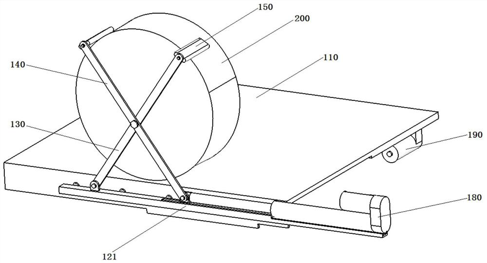
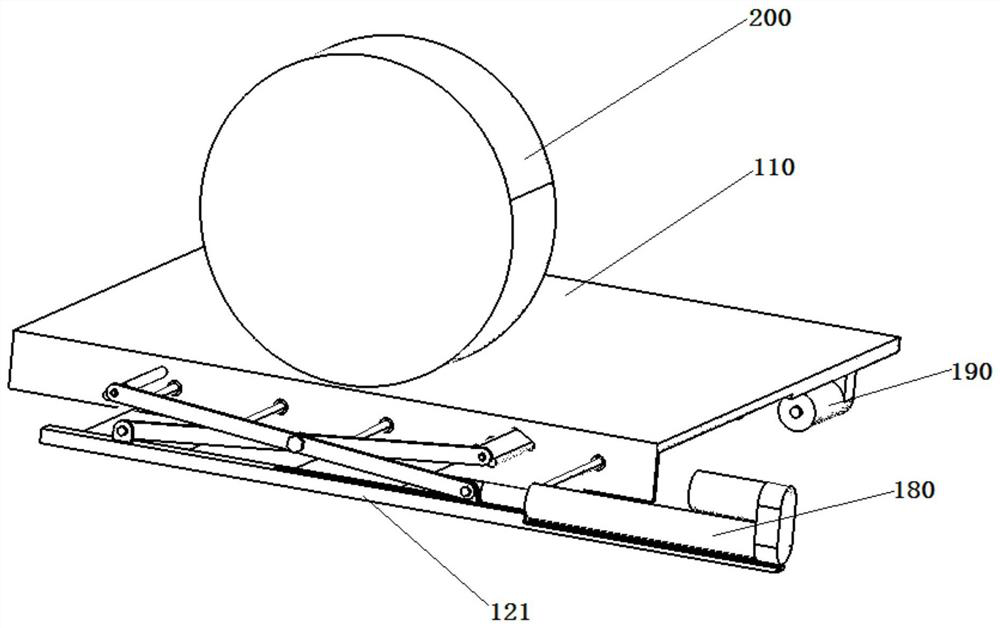
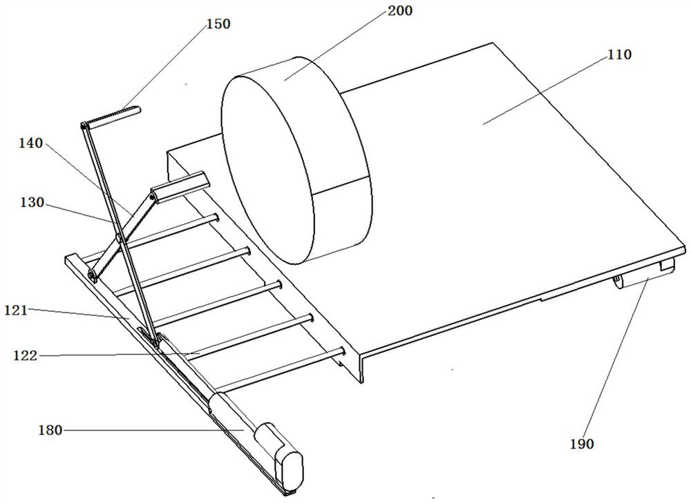
[0044] Such as Figure 1-6 As shown, the present invention provides an automatic fixing device based on a commercial vehicle unmanned transfer system, a support platform 110, a moving mechanism 120, a first cross arm 130, a second cross arm 140, a wheel fixing plate 150, a guide rail 160, and a fixed slide Block 170 , first drive mechanism 190 , second drive mechanism 180 .

[0045] The support platform 110 is fixed on the transport vehicle, at the bottom of the support platform 110, on one side of the support platform 110, a moving mechanism 120 is arranged, and at the bottom of the other side of the support platform 110, a first driving mechanism 190 is fixedly arranged, and the moving mechanism One end of 120 passes through the support platform 110 and connects the output...


PUM


Abstract

The invention discloses an automatic fixing device based on a commercial vehicle unmanned transfer system, and the device comprises a supporting platform which is fixedly disposed on a transport vehicle; a moving mechanism which penetrates through the supporting platform and can relatively move along the supporting platform; a first driving mechanism which s arranged at the bottom of the supporting platform and used for driving the moving mechanism; a guide rail which is arranged on the moving mechanism and is close to one end of the supporting platform; a fixed sliding block which is arranged on the guide rail in a matched mode and can relatively move along the guide rail; a first cross arm, wherein one end of the first cross arm is hinged to the fixed sliding block; a second cross arm, wherein one end of the second cross arm is hinged to the moving mechanism; and two wheel fixing plates which are rotationally connected to the other end of the first cross arm and the other end of the second cross arm respectively. Through the cooperation of the first cross arm, the second cross arm and the moving mechanism, the cross arms are expanded and contracted, then transfer wheels are fixed, and the transportation efficiency is improved.

Description

technical field [0001] The invention relates to an automatic fixing device based on a commercial vehicle unmanned transfer system, belonging to the field of commercial logistics transport vehicles. Background technique [0002] At present, in the process of using the means of transport to transport the automobile, the fixing of the automobile is mainly by manual use of a special fixing method. The main method is to use a wheel fixer and a strap (or a clip) to fix the wheel. The wheel retainer mainly prevents the front and rear movement of the wheel, and the strap is to prevent the left, right, up and down movement of the wheel. Its advantages: simple structure and low cost. Disadvantages: It needs to be done manually, and it cannot be automated. In the case of batch transportation, manual work is labor-intensive. At present, the requirements for the transportation efficiency of vehicles are getting higher and higher. It is very necessary to design a set of reliable automat...

Claims


Application Information

Patent Timeline
IPC IPC(8): B60P3/075B60P3/077B61D45/00
CPCB60P3/075B60P3/077B61D45/001
Inventor 沈传亮何可园高鹏邵煜李玥李雯
Owner JILIN UNIV
Learn More