Agility device for track system

A track and body technology, applied in the field of agile devices, can solve the problems of fixed lines, large space occupation, high cost, etc., and achieve the effect of preventing debris from being stuck

Pending Publication Date: 2021-05-25
万光军
View PDF0 Cites 0 Cited by
  • Summary
  • Abstract
  • Description
  • Claims
  • Application Information

AI Technical Summary

Problems solved by technology

However, the existing track technology also has some shortcomings, which affects the further development of track technology
Mainly reflected in its fixed line, difficult line expansion, slow line switching speed, large switching equipment, and high construction cost, etc.
In particular, the line switching equipment (turnout) takes up a huge space, so that in addition to the use of high-cost and space-consuming turnout technology in railways and subways to achieve line switching, other track technology application fields often use closed single-track tracks. Efficiency is greatly affected and it is difficult to expand the geographical coverage of rail applications
More common railcars such as entertainment venues can only run on a single-track track system, and each station can only be set in series. When the current vehicle stays on the track or the track needs maintenance, the rear vehicle can only wait. , resulting in the need to suspend the operation on all tracks. Even if some projects adopt track-changing technology, it is difficult to improve the efficiency of the track system due to slow speed and poor safety.

Method used


Image

  • Agility device for track system
  • Agility device for track system
  • Agility device for track system

Examples


Embodiment 1

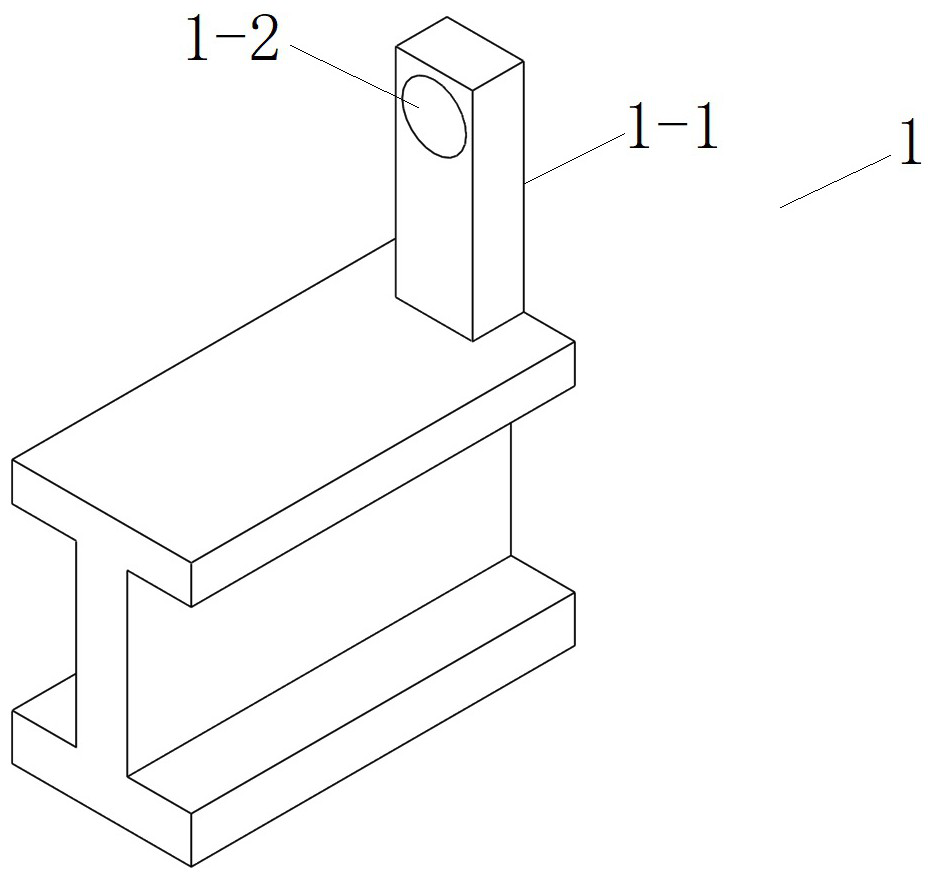
[0044] The track body of the front end 1 adopts a suspended single track, and the section is I-shaped.

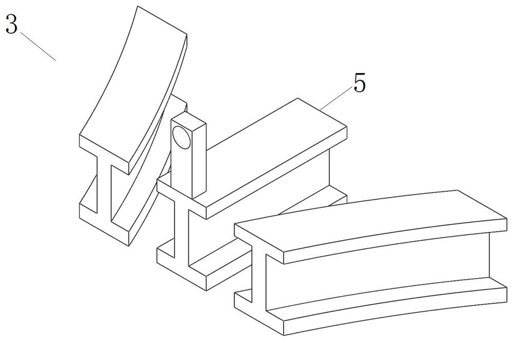
[0045] The rear end 3 has a multi-end rail composed of three single-end rails, and the longitudinal direction of the rail body is curved and / or straight.

[0046] The spinner 2 has a Mitsubishi cylindrical spinner body 2-1, and a spinner track 2-3 is provided on the side of the spinner body 2-1; The shaft hole 2-2; the screw track 2-3 are straight and curved respectively.

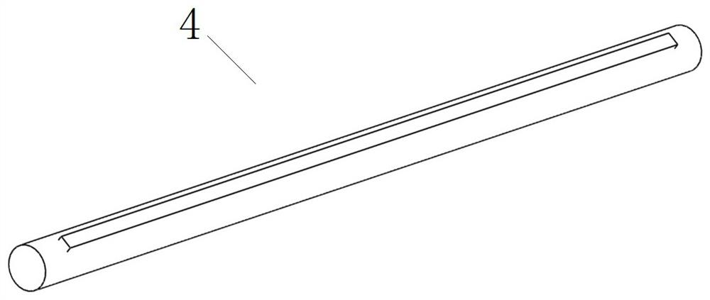
[0047] The front end 1, the spinner 2 and the rear end 3 are connected in series through the screw bearing 4 to form a one-to-three track switching mode, which realizes one-to-three or three-to-one switching on one device; cooperate with the control System and power energy and its access system, when the vehicle travels from the front end 1 or the rear end 3 to the spinner 2, the sensor in the controller senses the operating data of the relevant vehicle, and the communicator sends it to the control cent...

Embodiment 2

[0049] The track body of the front end 1 adopts a single set of load-bearing double tracks parallel to each other (conventional railway, subway, etc.).

[0050] The rear end 3 is provided with a multi-end rail, and the multi-end rail is composed of three single-end rail track bodies, and the longitudinal direction of the track body of the multi-end rail is curved and / or linear.

[0051] The spinner 2 is a rotatable device, the spinner 2 has a Mitsubishi cylindrical spinner body 2-1, and double spinner rails are arranged on the side of the spinner body 2-1; The middle part of the main body 2-1 is longitudinally provided with an installation shaft hole 2-2; the rails 2-3 of the screw joints are respectively straight and curved.

[0052] The front end 1, the spinner 2 and the rear end 3 are connected in series through the screw bearing 4 to form a one-to-three track switching, which realizes one-to-three or three-to-one switching on one device; cooperate with the control system ...

Embodiment 3

[0054] The single-end rail track body of the front end 1 adopts a suspended single track.

[0055] The rear end 3 is provided with a multi-end rail, and the multi-end rail is composed of two single-end rail track bodies, and the longitudinal direction of the track body is curved.

[0056] The spinner 2 has a cuboid spinner body 2-1, the side of the spinner body 2-1 is provided with a spinner track 2-3; the middle part of the spinner body 2-1 is longitudinally provided with a mounting shaft Holes 2-2; the tracks of the screw joints are straight and curved respectively.

[0057] The front end 1, the spinner 2 and the rear end 3 are connected in series through the bearing of the screw joint to form a one-to-two track switching mode, which realizes one-to-two or two-to-one switching on one device; it is used in conjunction with the control system And power energy and its access system, when the vehicle travels from the front end 1 or the rear end 3 to the spinner 2, the sensor in...


PUM


Abstract

The invention discloses an agility device for a track system, and relates to a track changing device, in particular to a track line agility device capable of achieving fast and free switching. The device comprises a front end, a rotary connector and a rear end, the front end and the rear end are connected in series through the rotary connector, and the front end and the rear end are connected with an existing track system or directly adopt an existing track; each of the front end and the rear end comprises a single-end rail and / or a multi-end rail and an end fixing piece; the rotary connector is a rotatable device and is provided with a screwing piece body, and screwing piece rails can be arranged on the side faces of the screwing piece body according to needs. A mounting shaft hole is longitudinally formed in the middle of the screwing piece body. The device has the advantages that the occupied space is small, the switching speed is high, automatic or manual control can be carried out, remote operation can be carried out, safety is high, one-to-many, many-to-one or many-to-many switching can be carried out on one device, the structure is simple, the maintenance is easy, and the running speed can be increased when a carrier passes through the device.

Description

technical field [0001] The invention relates to an agility device for a track system, which relates to a track change device, in particular to a track line agility device capable of fast and free switching. Background technique [0002] Rail technology is widely used in transportation, transportation, entertainment, equipment manufacturing and other fields. The track technology has the advantages of stable lines, strong anti-interference, centralized control, full use of three-dimensional space, relatively low requirements on geological conditions, moderate cost, and flexible selection of carrying capacity. But the existing track technology also has some shortcomings, which affects the further development of track technology. Mainly reflected in its fixed line, difficult line expansion, slow line switching speed, large switching equipment, and high construction cost. In particular, the line switching equipment (turnout) takes up a huge space, so that in addition to the use...

Claims


Application Information

Patent Timeline
Patent Type & Authority Applications(China)
IPC IPC(8): E01B7/10E01B7/14A63G7/00
CPCA63G7/00E01B7/10E01B7/14E01B2202/022
Inventor 万光军
Owner 万光军
Why Eureka
Try Eureka