Rail adjuster for rail transit based on permanent magnet motor and use method of rail adjuster
A track adjuster and permanent magnet motor technology, which is applied in the field of rail transit, can solve the problems of inaccurate track adjustment, time-consuming, and track shaking, and achieve the effects of increasing the fixing effect, saving adjustment time, and increasing accuracy
- Summary
- Abstract
- Description
- Claims
- Application Information
AI Technical Summary
Problems solved by technology
Method used
Image
Examples
Embodiment 1
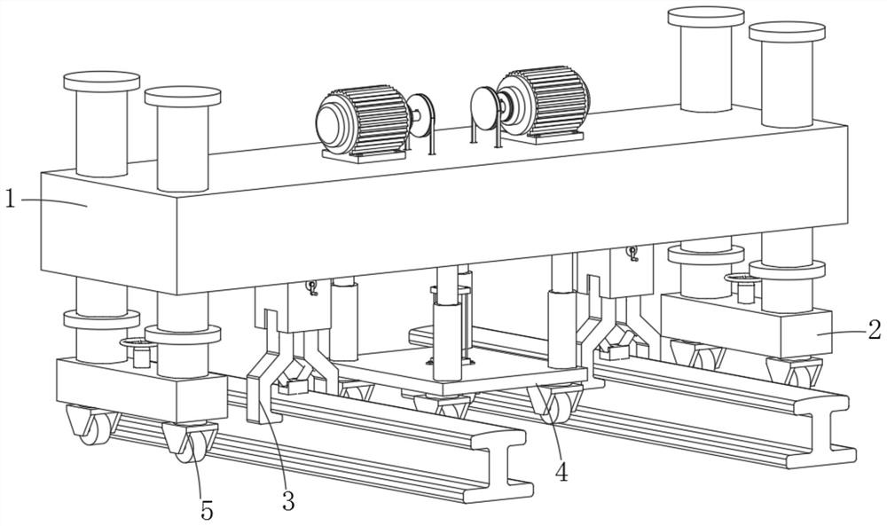
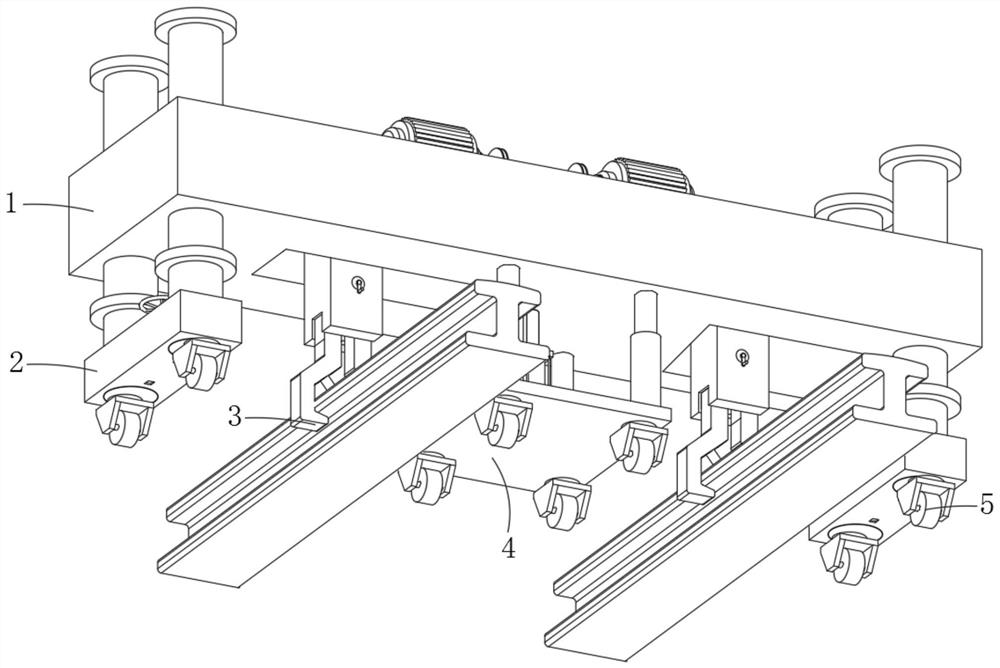
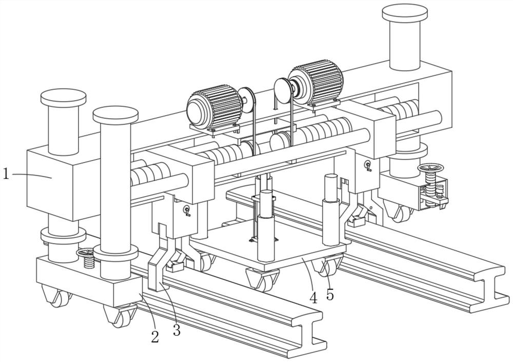
[0037] Embodiment one, with reference to Figure 1-4A track adjuster for rail transit based on a permanent magnet motor and a method of use thereof, comprising an adjustment mechanism 1, the center of the bottom of the adjustment mechanism 1 is provided with a moving mechanism 4, the adjustment mechanism 1 is used to adjust the distance between the tracks, and also It includes: a support mechanism 2 arranged at the bottom of the adjustment mechanism 1. There are two support mechanisms 2 in total. The support mechanism 2 plays a supporting role. Two supporting mechanisms 2 are respectively located on the left and right sides of the moving mechanism 4, the moving mechanism 4 is used to adjust the height of the adjusting mechanism 1, and the fixing mechanism 3 is arranged at the bottom of the adjusting mechanism 1. There are two fixing mechanisms 3, and the fixing mechanism 3 is used for For clamping the guide rail, the two fixing mechanisms 3 are respectively located on the left...
Embodiment 2
[0038] Embodiment two, refer to Figure 5 , 6 The two supporting mechanisms 2 all include installation boxes 201, and the upper surfaces of the two installation boxes 201 are fixedly connected with fixed rods 206 near the front and rear sides. The installation boxes 201 are used for fixing and can support the fixed rods 206 at the same time. The tops of the rods 206 are all fixedly connected with the second limit block 208, and the outer surfaces of the four fixed rods 206 are provided with the first limit block 207 near the bottom, the second limit block 208 and the first limit block 207 Both can play the role of limiting the fixed box 101, and the first limiting block 207 is located below the fixed box 101, the second limiting block 208 is located above the fixed box 101, and the outer surfaces of the four fixing rods 206 all slide Embedded in the four corners of the fixed box 101, the fixed rod 206 plays a role in positioning the movement of the fixed box 101, and the cent...
Embodiment 3
[0039] Embodiment three, refer to Figure 7-10 : the bottoms of the two moving blocks 103 are fixedly connected with an adjustment box 301, and the front and rear inner walls of the two adjustment boxes 301 are rotated to connect the rotating rod 302. The adjusting box 301 is used for installation and fixing, and one end of the two rotating rods 302 is connected Fixedly connected with a rocker 304, the rocker 304 is convenient for the staff to adjust. The middle part of the outer surface of the two rotating rods 302 is fixedly connected with a rotating gear 303. The rotating rod 302 is used to fix and support the rotating gear 303. The front and rear of the two adjustment boxes 301 Driven gears 305 are rotatably connected between the inner walls, and the two driven gears 305 are respectively meshed with two rotating gears 303. The rotation of the rotating gears 303 can drive the driven gears 305 to rotate. The front and rear inner walls of the two adjustment boxes 301 There ar...
PUM
 Abstract
Description
Claims
Application Information
 - R&D
- Intellectual Property
- Life Sciences
- Materials
- Tech Scout
- Unparalleled Data Quality
- Higher Quality Content
- 60% Fewer Hallucinations
Browse by: Latest US Patents, China's latest patents, Technical Efficacy Thesaurus, Application Domain, Technology Topic, Popular Technical Reports.
© 2025 PatSnap. All rights reserved.Legal|Privacy policy|Modern Slavery Act Transparency Statement|Sitemap|About US| Contact US: help@patsnap.com


