
Multistage self-adaptive composite inertial-capacitance vibration damping device, method and structure

A vibration damping device and self-adaptive technology, which is applied to building components, earthquake resistance, building types, etc., can solve the problems of reducing the effective utilization rate of collision energy-consuming devices and the inability to adjust the collision gap, so as to achieve good energy consumption effect and reduce additional The effect of high quality and control precision

Active Publication Date: 2021-05-25
SHANDONG ELECTRIC POWER ENG CONSULTING INST CORP
View PDF12 Cites 3 Cited by
  • Summary
  • Abstract
  • Description
  • Claims
  • Application Information

AI Technical Summary

Problems solved by technology

In addition, the inventors found that in the collision energy dissipation technology, the collision gap has a great influence on the energy dissipation effect, but most of the collision energy dissipation technologies currently used are fixed collision gaps, and it is impossible to adjust the collision according to the different degrees of vibration response of the structure. clearance, which reduces the effective utilization of the collision energy-dissipating device

Method used


Image

  • Multistage self-adaptive composite inertial-capacitance vibration damping device, method and structure
  • Multistage self-adaptive composite inertial-capacitance vibration damping device, method and structure
  • Multistage self-adaptive composite inertial-capacitance vibration damping device, method and structure

Examples


Embodiment Construction

[0044] The present invention will be further described below in conjunction with the accompanying drawings and embodiments.

[0045]It should be noted that the following detailed description is exemplary and intended to provide further explanation of the present invention. Unless defined otherwise, all technical and scientific terms used herein have the same meaning as commonly understood by one of ordinary skill in the art to which this invention belongs.

[0046] It should be noted that the terminology used here is only for describing specific embodiments, and is not intended to limit exemplary embodiments according to the present invention. As used herein, unless the context clearly dictates otherwise, the singular is intended to include the plural, and it should also be understood that when the terms "comprising" and / or "comprising" are used in this specification, they mean There are features, steps, operations, means, components and / or combinations thereof.

[0047] In ...


PUM


Abstract

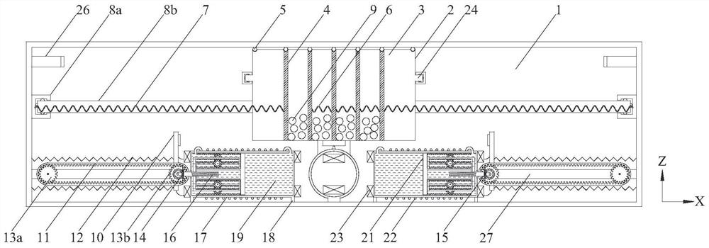
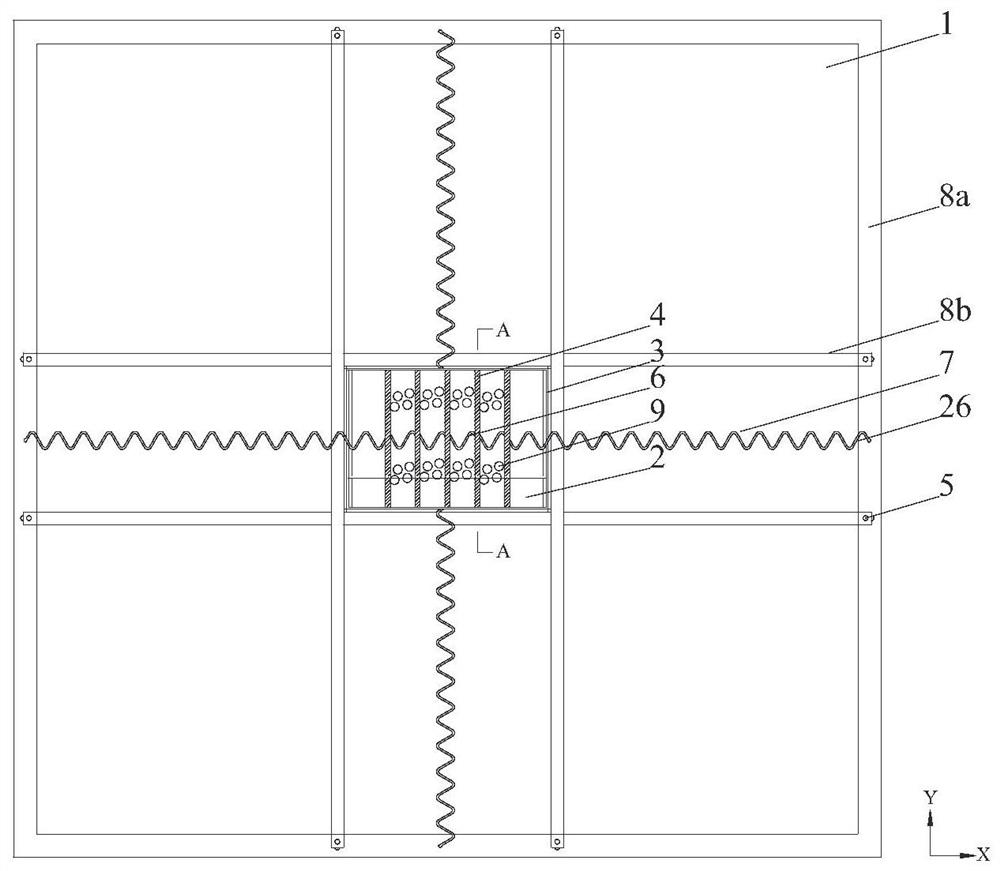
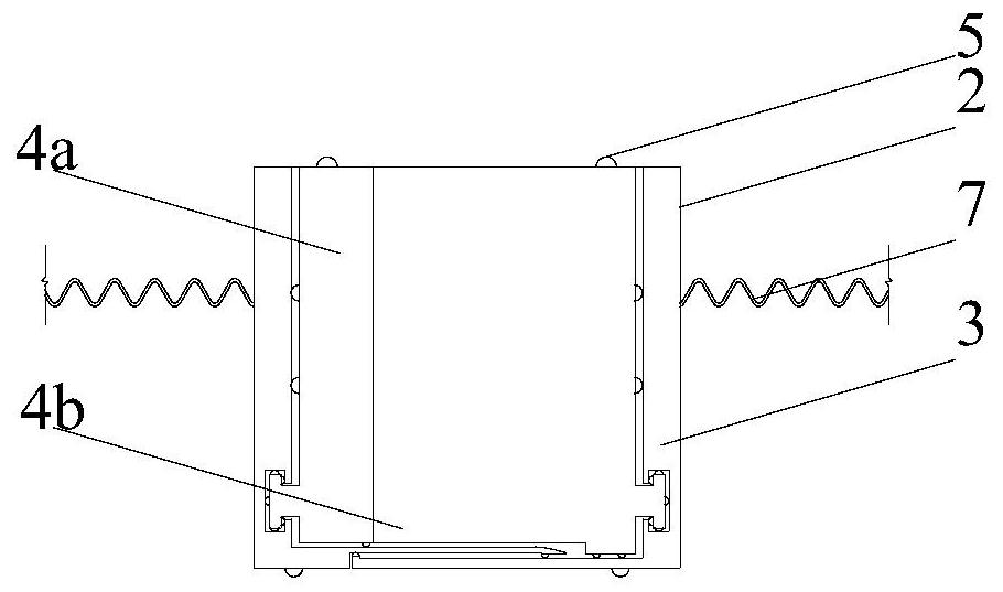
The invention provides a multistage self-adaptive composite inertial-capacitance vibration damping device, method and civil engineering structure. The multistage self-adaptive composite inertial-capacitance vibration damping device comprises a mass body, wherein the mass body comprises a telescopic box body capable of moving in the Y direction, a plurality of telescopic plates which are placed in the Y direction and can move in the X direction are arranged in the telescopic box body, the telescopic plates are connected through linkage springs, and the telescopic plate on the outermost side is connected with a first-stage guide rail through a tuning spring, so that self-adaptive collision of collision balls between the telescopic plates in the X direction is realized; a magnetorheological hydraulic energy dissipation mechanism comprises an energy dissipation box, wherein the energy dissipation box is provided with a multistage sliding frame and a piston, the energy dissipation box is fully filled with magnetorheological fluid, the piston can slide along a rack on the inner wall of the energy dissipation box, and excitation coils are arranged at the two ends of the energy dissipation box; a transmission mechanism comprises a transmission plate, wherein the bottom of the transmission plate is fixed on the rack, and the transmission plate is connected to the inner side wall of a working box through a reset spring; and a displacement sensor is further installed on the transmission plate, is used for monitoring the displacement of the transmission plate, and is connected with the excitation coils through an electromagnetic control circuit.

Description

technical field [0001] The invention belongs to the field of vibration control of towering and large-span structures, and in particular relates to a multi-stage self-adaptive compound inertial vibration damping device, method and structure. Background technique [0002] The statements in this section merely provide background information related to the present invention and do not necessarily constitute prior art. [0003] With the development of high-rise and long-span structures towards diversified functions and complex structures, the vibration of structures under environmental loads is becoming more and more serious. Unfavorable vibrations will affect the performance and life of structures, and vibration reduction control measures can effectively solve the problem. Safety issues during the entire life of engineering structures to reduce the impact of disasters. Among them, the dynamic vibration absorption type vibration reduction device achieves the purpose of dynamic v...

Claims


Application Information

Patent Timeline
IPC IPC(8): E04B1/98E04H9/02
CPCE04B1/98E04H9/021
Inventor 刘勇魏珍中李林李艳丽宋嘉庆李洪旺郑玉超李文霞刘蕊李天天刘娜姜洋彬
Owner SHANDONG ELECTRIC POWER ENG CONSULTING INST CORP
Learn More