Overhaul climbing ladder for hydraulic engineering
A technology for water conservancy projects and climbing ladders, applied to ladders, applications, household appliances, etc., can solve the problems of slipping and falling during maintenance, achieve high safety, increase friction, and prevent splashing on the shoe surface
- Summary
- Abstract
- Description
- Claims
- Application Information
AI Technical Summary
Problems solved by technology
Method used
Image
Examples
Embodiment 1
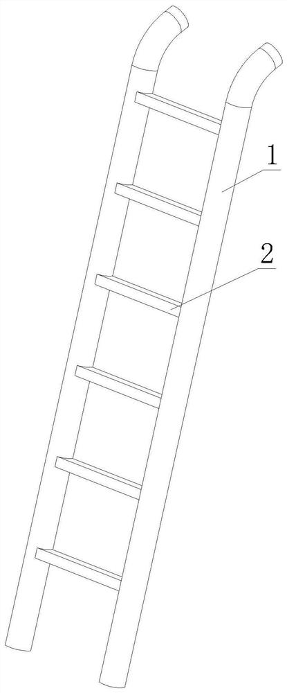
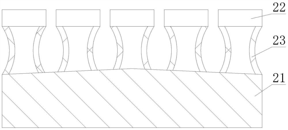
[0024] like figure 1 - image 3 As shown, the present invention provides a maintenance climbing ladder for water conservancy projects, comprising side fixed rods 1, the number of side fixed rods 1 is two, and a climbing rod 2 is fixedly connected between the two side fixed rods 1. The inside of the climbing pole 2 is provided with a bottom block 21, the upper end surface of the bottom block 21 is provided with a protrusion, the top of the bottom block 21 is provided with a stepping block 22, and the lower end of the stepping block 22 is symmetrically provided with a compressed air structure 23, and the compressed air structure 23 is an arc. Shape design, which is used to limit the deformation direction of the compressed air structure 23, the bottom block 21 and the tread block 22 are fixedly connected through the compressed air structure 23, and this design is used to form a sealed area between the compressed air structure 23, the stepped block 22, and the bottom block 21 , i...
Embodiment 2
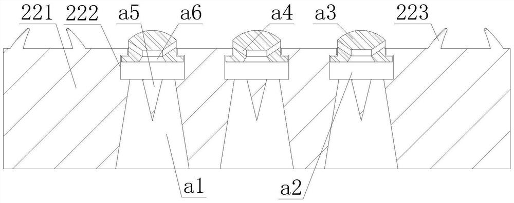
[0027] like Figure 3-4 As shown, on the basis of Embodiment 1, the present invention provides a technical solution: the inside of the cleaning structure 222 is provided with a compressed air groove a1, and the upper end of the compressed air groove a1 is connected with an air cavity a2, and the internal sliding card of the air cavity a2 The sealing block a3 is connected, and the middle part of the lower end of the sealing block a3 is provided with a pressure air groove a6 and an air flow channel a4. The air flow channel a4 is a spiral upward design. The passage a4 is arranged at the outer edge of the air-pressing groove a6 and communicated with each other. An extruding block a5 is arranged at the end of the air-pressing groove a1 close to the air cavity a2. When the air-flow passes through, increase the center of the air-flow, so that the sealing block a3 will rise quickly.
[0028] In this embodiment, through the arrangement of the compressed air groove a1 and the extrusion...
Embodiment 3
[0030] like Figure 5 As shown, on the basis of Embodiment 1, the present invention provides a technical solution: preferably, the air pressure structure 23 is provided with an air pressure rubber block 231, and one side of the lower end of the air pressure rubber block 231 is fixedly connected with a limit block 234, The upper end of the stop block 234 is snap-fitted with a protective rubber 235, and the lower end of the air pressure rubber block 231 and the lower end of the stop block 234 are provided with a cleaning hole 236, and the cleaning hole 236 is provided with a downward slope, so that the ejected The gas keeps blowing in an obliquely downward direction, thereby speeding up the flow of muddy water on the bottom block 21 . Air intake holes 232 begin to be formed above the middle part of the air pressure rubber block 231 , and a choke block 233 is arranged inside the air intake holes 232 .
[0031] Wherein, a connection block d1 is arranged inside the flow blocking bl...
PUM
 Abstract
Description
Claims
Application Information
 - R&D
- Intellectual Property
- Life Sciences
- Materials
- Tech Scout
- Unparalleled Data Quality
- Higher Quality Content
- 60% Fewer Hallucinations
Browse by: Latest US Patents, China's latest patents, Technical Efficacy Thesaurus, Application Domain, Technology Topic, Popular Technical Reports.
© 2025 PatSnap. All rights reserved.Legal|Privacy policy|Modern Slavery Act Transparency Statement|Sitemap|About US| Contact US: help@patsnap.com


