
Transmission, power assembly and power equipment

A technology of transmission and synchronizer, which is applied in the field of vehicle engineering and can solve the problems of increased number of gear pairs, unfavorable placement, and large center distance

Pending Publication Date: 2021-05-25
SUOTE TRANSMISSION EQUIP
View PDF0 Cites 0 Cited by
  • Summary
  • Abstract
  • Description
  • Claims
  • Application Information

AI Technical Summary

Problems solved by technology

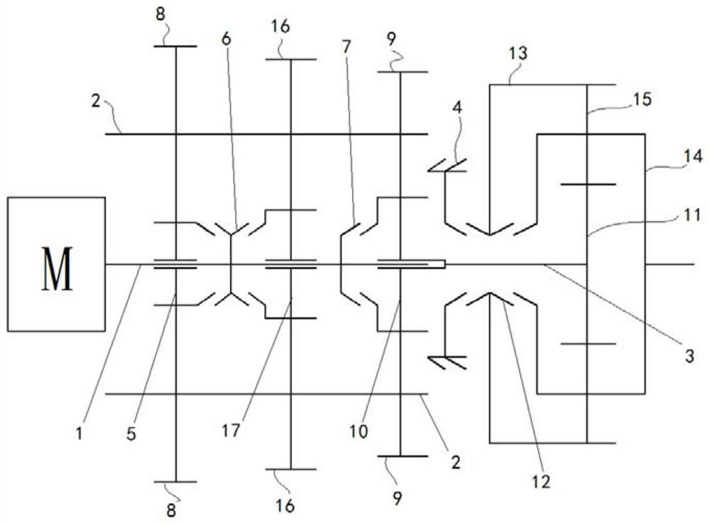
However, in the above-mentioned shifting methods, a gear needs to be provided with a corresponding set of gear pairs. When the speed ratio is relatively large, according to the characteristics of the gear meshing transmission, the center distance between the input shaft and the output shaft is too large, which in turn causes the transmission to move radially. When the volume increases, or the required gears increase, the number of gear pairs increases, which increases the overall weight of the transmission, which is not conducive to its placement in the vehicle

Method used


Image

  • Transmission, power assembly and power equipment
  • Transmission, power assembly and power equipment
  • Transmission, power assembly and power equipment

Examples


Embodiment 1

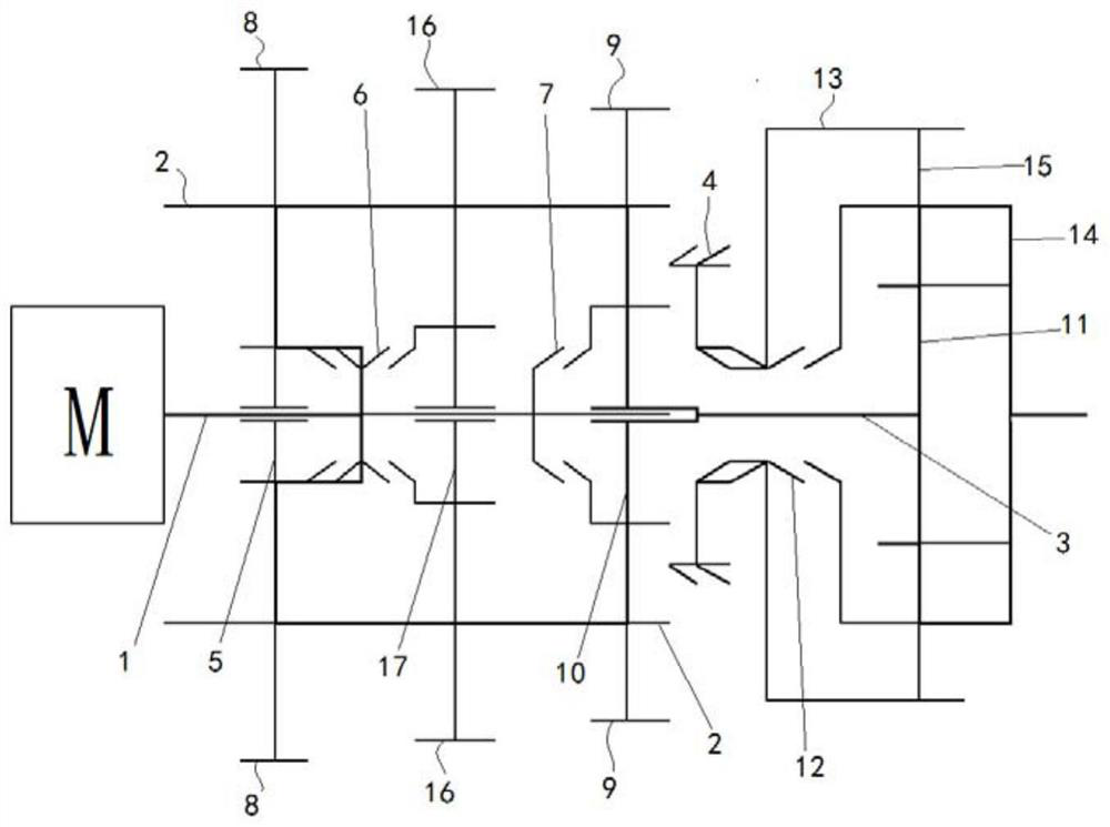
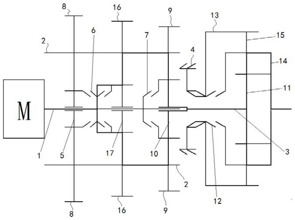
[0044] Such as Figure 1 to Figure 7 As shown, a transmission provided in this embodiment includes: a housing 4; an input shaft system, the input shaft system includes: an input shaft 1; at least one first main transmission member 5, which is spaced apart from the input shaft along the axial direction. On the shaft 1; at least one first synchronizer 6 is arranged on the input shaft 1 adjacent to the first main transmission member 5, and the first synchronizer 6 is combined or separated from the first main transmission member 5; and is arranged on the input shaft 1 The second synchronizer 7; the intermediate shaft system, the intermediate shaft system includes: at least one intermediate shaft 2, arranged in parallel with the input shaft 1; at least one first follower 8, fixed on the intermediate shaft 2, the first driven 8 is matched with the first main transmission member 5; and the second main transmission member 9 fixed on the intermediate shaft 2; the planetary gear train, ...

Embodiment 2

[0068] This embodiment provides a transmission, including: a housing 4; an input shaft system, the input shaft system includes: an input shaft 1; at least one first main transmission member 5, fixed on the input shaft 1 at intervals along the axial direction; And the second synchronizer 7 arranged on the input shaft 1; the intermediate shaft system, the intermediate shaft system includes: at least one intermediate shaft 2, arranged in parallel with the input shaft 1; at least one first follower 8, spaced and sleeved in the middle On the shaft 2, the first driven member 8 cooperates with the first main transmission member 5; at least one first synchronizer 6 is arranged on the intermediate shaft 2 adjacent to the first driven member 8, and the first synchronizer 6 and the first The driven member 8 is combined or separated; and the second main transmission member 9 fixed on the intermediate shaft 2; the planetary gear train, the planetary gear train includes: the output shaft 3, ...

Embodiment 3

[0071] This embodiment provides a power assembly, including: a motor; and the transmission of any one of the above-mentioned embodiment 1 or embodiment 2, the output end of the motor is connected to the input shaft 1, and has all its technical advantages, No more details here.


PUM


Abstract

The invention relates to the technical field of vehicle engineering, in particular to a transmission, a power assembly and power equipment. The transmission comprises: a shell, an input shaft system, intermediate shaft systems and a planetary gear system, wherein the planetary gear system comprises an output shaft, a sun gear and a third synchronizer, a second driven part is arranged on the output shaft and cooperates with a second driven part, and a second synchronizer is combined with or separated from the second driven part, and the third synchronizer is arranged on a gear ring, and can be combined with or separated from the shell and a planet carrier. Compared with the prior art, the use of transmission pairs is at least reduced, so that the weight of the whole transmission can be effectively reduced.

Description

technical field [0001] The invention relates to the technical field of vehicle engineering, in particular to a transmission, a power assembly, and power equipment. Background technique [0002] Under the strategic needs of reducing carbon emissions, promoting the development and utilization of renewable energy, and realizing energy diversification, electric vehicles have gradually become a green choice for travel and transportation. [0003] Electric vehicles are mainly powered by on-board power supplies, and use motors to drive vehicles to run. Electric vehicles are similar to fuel vehicles with transmissions. In different driving scenarios, the speed requirements of the vehicle are very different. Therefore, it is necessary to configure a transmission between the motor and the drive shaft of the vehicle to realize the adjustment of the vehicle speed. Make sure to match the appropriate driving speed in different scenarios, so that the motor can be in the high-efficiency zo...

Claims


Application Information

Patent Timeline
Patent Type & Authority Applications(China)
IPC IPC(8): F16H3/44
CPCF16H3/44
Inventor 王福军李福文
Owner SUOTE TRANSMISSION EQUIP
Learn More