Air source heat pump

An air-source heat pump and accommodating space technology, applied in the field of heat pumps, can solve the problems of insufficient stability of the product center of gravity, low adaptability to complex water quality, high post-maintenance costs, etc., to protect the stability of the structure, reduce the impact of stress, and prolong the service life. Effect

Pending Publication Date: 2021-05-25
QINGDAO HAIER NEW ENERGY ELECTRIC APPLIANCE +2
View PDF0 Cites 0 Cited by
  • Summary
  • Abstract
  • Description
  • Claims
  • Application Information

AI Technical Summary

Problems solved by technology

[0003] Due to the limitations of the current body structure, the air source heat pump chiller with small power and side outlet air integration generally adds a condenser (water side) on the top of the body on the basis of the existing air conditioner products, but this design will cause The center of gravity of the whole machine is too high, resulting in insufficient stability of the center of gravity of the product
In another solution of the prior art, the space of the compressor compartment in the machine body is relatively large, so the condenser (water side) is placed in the compressor compartment, but there is also the problem that the center of gravity is biased to the side of the compressor, resulting in an unstable structure Technical problems; in addition, the selection of this scheme will lead to limited selection of condensers, and only casing heat exchangers or plate heat exchangers can be selected. There is a big gap, and although the plate heat exchanger is better in heat transfer, its adaptability to complex water quality is lower, requiring higher installation conditions and higher maintenance costs

Method used


Image

  • Air source heat pump
  • Air source heat pump
  • Air source heat pump

Examples


Embodiment 1

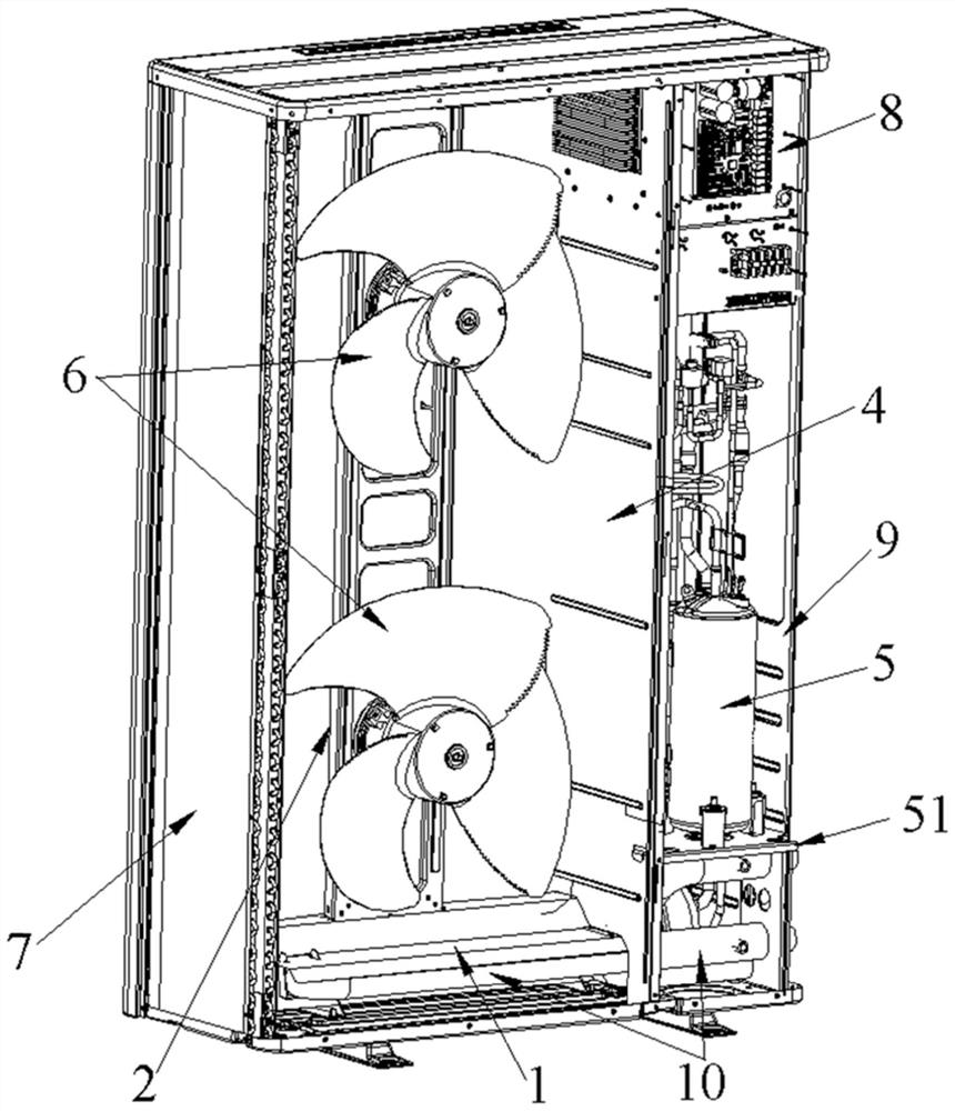
[0058] In this example, if figure 1 As shown, an air source heat pump is provided, including:

[0059] The shell 9 is provided with a middle partition 4 that separates the internal accommodation space;

[0060] The fan 6 is arranged on the fan frame 2 on one side of the middle partition 4;

[0061] The evaporator 7 is arranged along the side wall and the rear wall of the casing 9, and is on the same side of the middle partition 4 as the fan 6;

[0062] The compressor 5 and the electric control element 8 are located on the other side of the middle partition 4 opposite to the fan 6;

[0063] The air source heat pump also includes a condenser 10 covering the inner bottom of the housing 9 and passing through the middle partition 4 . The condenser 10 is provided with a guard plate 1 against the middle partition 4 .

[0064] In this embodiment, the condenser (water side) in the heat pump is arranged at the bottom of the body, which can lower the center of gravity of the whole mac...

Embodiment 2

[0074] The difference between this embodiment and embodiment 1 is:

[0075] In this embodiment, the fan frame 2 is assembled on the top of the condenser 10 .

[0076] In this embodiment, since the condenser 10 occupies the bottom space of the machine body, the fan rack cannot be used in the prior art, that is, the fan rack is directly connected to the chassis of the machine body. In view of this, in this embodiment, the fan bracket 2 is installed on the condenser 10 in view of space utilization and installation fastness. Specifically, screw holes can be provided on the side of the bottom of the fan frame 2 to correspond to the screw holes of the vertical plates on the upper surface of the condenser 10 .

[0077] Other implementation modes of this embodiment are the same as embodiment 1.

Embodiment 3

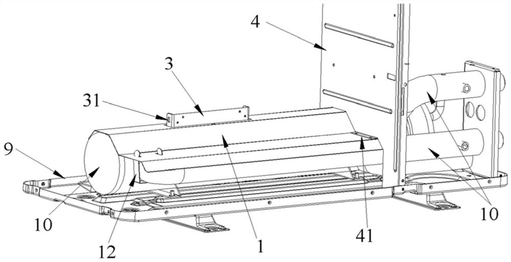
[0079] This embodiment is a further improvement to the air source heat pump on the basis of Embodiment 1, specifically including:

[0080] In this example, if figure 2 As shown, the heat pump also includes a support 3 assembled with the bottom of the fan frame 2 , and the support 3 is installed on the top of the guard plate 1 .

[0081]In this embodiment, when a plurality of fans 6 are installed on the fan frame 2, or the height of the shell of the machine body is high, a support structure can be added on the guard plate 1 to increase the bearing capacity of the fan frame. The support 3 can not only increase the installation fastness of the fan frame 2, but also reduce the influence of the stress generated when the fan 6 is working, thereby prolonging the service life of the guard plate 1.

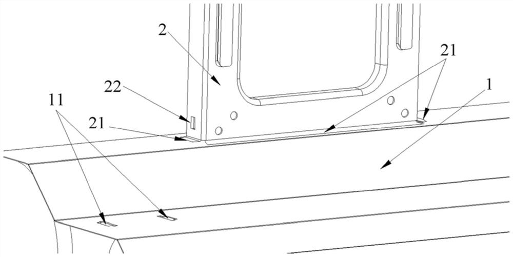
[0082] In this example, if Figure 4 As shown, at least two opposite sides of the support 3 are provided with bayonets 31, and the bottom of the fan frame 2 is provided with claws 22 co...


PUM


Abstract

The invention discloses an air source heat pump which comprises a shell, a fan, an evaporator, a compressor and an electric control element. The shell is provided with a middle partition plate for dividing an internal containing space. The fan is arranged on a fan frame on one side of the middle partition plate. The evaporator is arranged along the side wall and the rear wall of the shell, and the evaporator and the fan are located on the same side of the middle partition plate. The compressor and the electric control element are both arranged on the other side, opposite to the fan, of the middle partition plate. The air source heat pump further comprises a condenser which covers the inner bottom of the shell and penetrates through the middle partition plate, and a protection plate abutting against the middle partition plate is arranged on the condenser. According to the air source heat pump provided by the invention, the condenser is arranged at the bottom of a machine body and penetrates through a fan bin and a press bin, and on the premise that the stability of the gravity center structure of the whole machine is guaranteed, the containing space in the machine shell is fully utilized. In addition, the invention further provides the protection plate for protecting the condenser, the protection plate and the fan frame are in an assembly relationship, the stability of the machine body structure is further improved, meanwhile, noise reduction and shock absorption functions are achieved, and the air source heat pump is suitable for application and popularization.

Description

technical field [0001] The invention belongs to the field of heat pumps, and in particular relates to an air source heat pump. The air source heat pump adopts an integrated machine structure, and the condenser is arranged at the bottom of the body, which is conducive to the stability of the whole machine and can increase the stability of the wall-mounted installation. In addition, the body also includes a guard plate that protects the condenser and is assembled with the fan frame, which not only further increases the stability of the body structure, but also has the function of reducing noise and shock. Background technique [0002] With the development of heat pump industry applications, the design of heat pump products is also diversified. For larger side air source heat pump chillers, the design is generally based on the direction of the modular unit in the early stage, and the top air is generally designed. As for the air source heat pump chillers with side air outlet, ...

Claims


Application Information

Patent Timeline
IPC IPC(8): F25B30/06
CPCF25B30/06
Inventor 李建民陈炳泉崔怀银康乐高家富侯梅梅管祥华李羲龙
Owner QINGDAO HAIER NEW ENERGY ELECTRIC APPLIANCE
Why Eureka
Try Eureka