Loading tool assembly for bearing testing machine and method for loading test bearing

A bearing test and axial loading technology, applied in the direction of mechanical bearing testing, etc., can solve the problems affecting the accuracy of test results, unable to guarantee installation accuracy, not suitable for quick disassembly, etc., to solve automation and rapid installation, and improve data accuracy. And, to solve the effect of easy damage

Active Publication Date: 2021-05-25
中浙高铁轴承有限公司
View PDF13 Cites 0 Cited by
  • Summary
  • Abstract
  • Description
  • Claims
  • Application Information

AI Technical Summary

Problems solved by technology

[0004] However, in this technical solution, the test bearing needs to be fixed by several bolts, which is difficult to disassemble and cannot guarantee the installation accuracy, which affects the accuracy of the test results, and is not suitable for quick disassembly of the bearing test.

Method used


Image

  • Loading tool assembly for bearing testing machine and method for loading test bearing
  • Loading tool assembly for bearing testing machine and method for loading test bearing
  • Loading tool assembly for bearing testing machine and method for loading test bearing

Examples


Embodiment 1

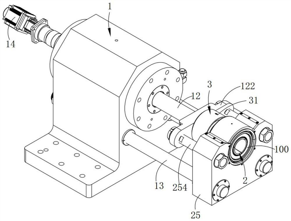
[0052] Such as figure 1 As shown, a loading tool assembly for a bearing testing machine includes a power assembly 1, an expansion assembly 2, and an axial loading assembly 3 arranged on one side of the expansion assembly 2; the expansion assembly 2 is arranged on the bearing to be tested The inner diameter of the axial loading assembly 3 is arranged at the output end of the power assembly 1; the power assembly 1, the expansion assembly 2 and the axial loading assembly 3 are arranged coaxially;

[0053] When working, after the axial loading assembly 3 pre-fixes the bearing 100 to be tested, driven by the power assembly 1, the compression expansion assembly 2 tightens the inner diameter of the bearing 100 to be tested and the support shaft 200, and at the same time, the axial loading assembly 3 Axial loading of the bearing;

[0054] It should be noted that the support shaft 200 is used to support the bearing 100 to be tested and to drive the bearing 100 to be tested to rotate; ...

Embodiment 2

[0085] A method for loading and testing bearings using a loading tooling assembly for a bearing testing machine described in the technical solution of the first embodiment above includes the following steps:

[0086] Step 1, pre-installation of the bearing to be tested 100, the bearing to be tested 100 is installed on the working position 251 on the support seat 25; 2521 perform pre-positioning;

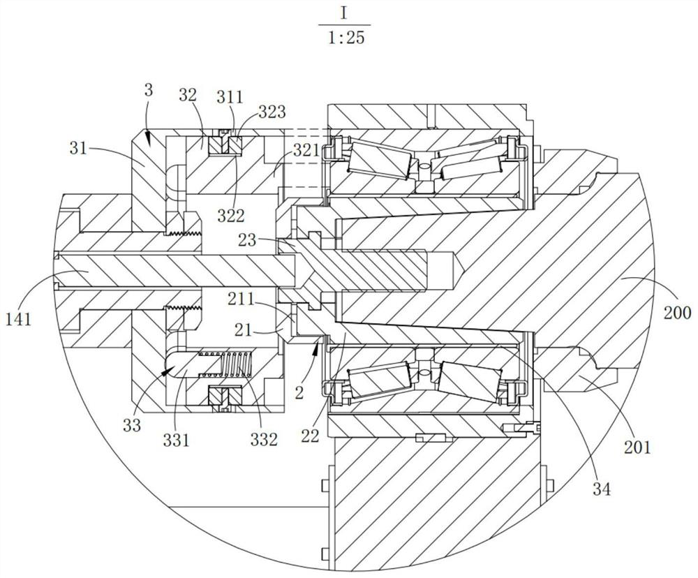
[0087] Step 2: pre-fix the bearing 100 to be tested, the inner ring loading die 32 protrudes from the outer ring loading die 31 under the action of the limit assembly, start the power assembly 1, drive the axial loading assembly 3 to move to the right, and make the bearing 100 to be tested Cooperate with the support shaft 200, and at the same time, the boss 321 of the inner ring loading die 32 is in contact with the inner ring of the bearing to be tested 100, the position of the inner ring and the outer ring of the bearing to be tested 100 is adjusted, and the axial loading assembly ...


PUM


Abstract

The invention provides a loading tool assembly for a bearing testing machine. The loading tool assembly comprises a power assembly, a pressing and expanding assembly and an axial loading assembly arranged on one side of the pressing and expanding assembly. The pressure expansion assembly is arranged at the inner diameter of the bearing to be detected, and the axial loading assembly is arranged at the output end of the power assembly; the axial loading assembly is used for pre-fixing the bearing to be tested, the supporting shaft is combined for positioning, after the bearing to be tested is circumferentially positioned, the pressing and expanding assembly is used for expanding the inner diameter of the bearing to be tested, and after an inner ring and an outer ring of the bearing are respectively positioned, the inner ring is expanded, so that accurate installation is realized; the pressing and expanding assembly can be rapidly disassembled through the disassembling driving part, and rapid disassembling and pressing and expanding are achieved in cooperation with the locking part arranged on the conical surface.

Description

technical field [0001] The invention relates to high-speed rail bearing testing equipment, in particular to a method for loading and testing bearings using a loading tool assembly for a bearing testing machine. Background technique [0002] The establishment of the routine test link of high-speed rail bearings is to ensure that there will be no problems in the loading of domestic high-speed rail bearings. The research has practical significance. The installation structure of the test bearing and the shaft is an interference structure, and the interference is about 0.05mm. If cold pressing is adopted, friction damage to the inner ring of the bearing will inevitably be caused during the assembly and disassembly process; Routine tests are mainly short-term tests, generally ranging from 10 to 60 minutes. Therefore, the experimental process must not only ensure the accuracy of installation, but also ensure the realization of non-destructive testing. At the same time, it is necess...

Claims


Application Information

Patent Timeline
Patent Type & Authority Applications(China)
IPC IPC(8): G01M13/04
CPCG01M13/04
Inventor 陈仁波张佩思冯小兰朱群涛
Owner 中浙高铁轴承有限公司
Why Eureka
Try Eureka