
Wiring design system and wiring design method for power grid

A wiring design and design system technology, applied in computer-aided design, calculation, electrical digital data processing, etc., can solve the problems of waste of investment, low utilization rate, and lack of accurate budget for cable requirements.

Pending Publication Date: 2021-05-25
国网山东省电力公司聊城供电公司
View PDF4 Cites 0 Cited by
  • Summary
  • Abstract
  • Description
  • Claims
  • Application Information

AI Technical Summary

Problems solved by technology

In the design stage, the designer only reflects the starting point, end point and model of the cable in the design drawing; in the cable laying stage, the relevant technicians lay the cable in the cable channel that has been erected according to the rough calculation of the cable direction and length. The radiation path and cable length, in this process, rely more on construction experience, and the demand for cables often deviates due to lack of accurate budget, resulting in a huge waste of investment
[0003] The erection of cable channels often belongs to the professional civil engineering business category, and is generally completed synchronously with the main building of the substation, that is, the cable channels are erected according to a unified standard in the cable room, cable trench or cable shaft that has been designed on the architectural drawings, which causes cable channels and cable laying. The design of the cable is completely out of touch. In the later stage of cable laying, the cable channel space is often insufficient or the utilization rate is not high. In the cable laying stage, it is difficult to adjust the cable channel at any time according to the construction needs, which causes great inconvenience to the construction.

Method used


Image

  • Wiring design system and wiring design method for power grid
  • Wiring design system and wiring design method for power grid

Examples


Embodiment 1

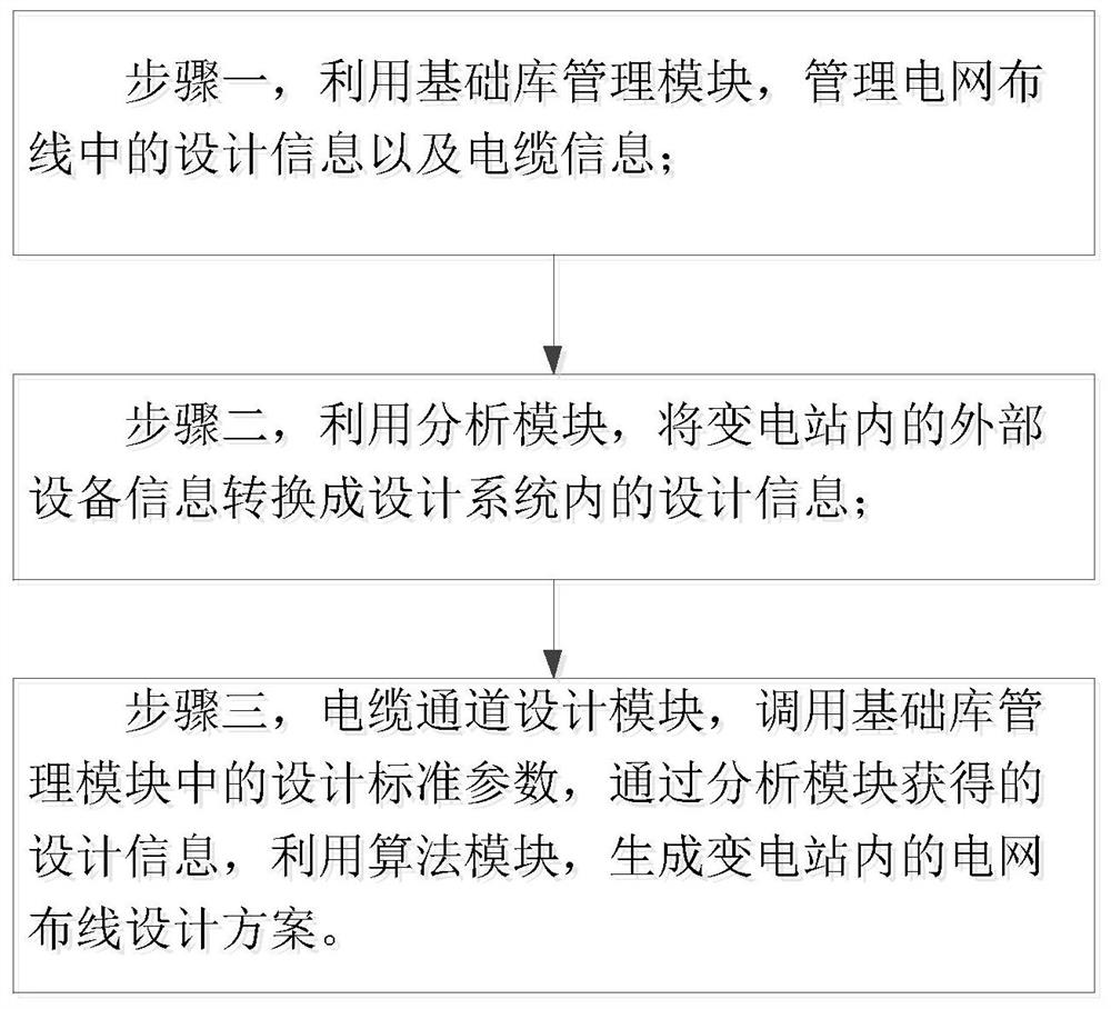
[0041] Refer to attached figure 1 As shown, a wiring design system for power grid in this embodiment includes:

[0042] An analysis module, the analysis module converts the input external device information into design information that can be recognized by the design system;

[0043] A basic library management module, the basic library management module is used to store design information and cable channel information, including but not limited to cable parameters and design standard parameters;

[0044] An algorithm module, the algorithm module integrates several algorithms, and among the several algorithms, each of the algorithms corresponds to a different wiring method;

[0045] The cable channel design module calls the design standard parameters, and combines the design information obtained by the algorithm module and the analysis module to automatically generate a design scheme.

[0046] In this embodiment, by combining multiple module designs, not only the characteristic...

Embodiment 2

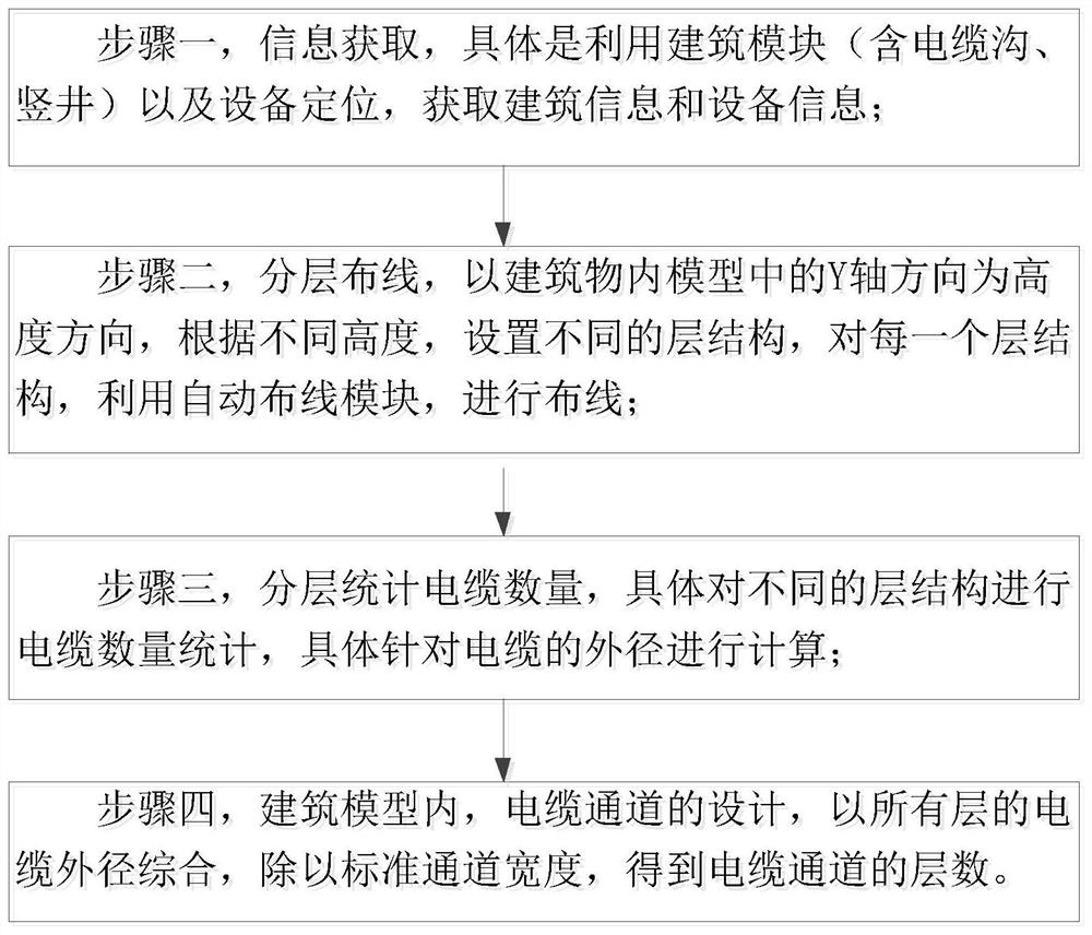
[0076] In this embodiment, the introduction is mainly combined with specific implementation operations.

[0077] First, obtain the building model of the substation through the 3D design software (focusing on building structures related to cable laying, such as cable rooms, cable trenches or cable shafts), that is, refer to the attached figure 2 The building modules in the building (including cable trenches and shafts); at the same time, use positioning software to realize the positioning of equipment in the building, and then obtain the positioning of the equipment in the building.

[0078] Combining the building model with the equipment positioning information, there is not only the information of the building itself, but also the location information of the equipment, which provides a basic basis for the initial path of the subsequent cable wiring design.

[0079] When designing the wiring, it is necessary to carry out the three-dimensional wiring of the cable layered accor...


PUM


Abstract

The invention discloses a wiring design system and design method for a power grid. The design system comprises an analysis module, wherein the analysis module is used for converting input external equipment information into design information which can be identified by the design system; a basic library management module which is used for storing design information and cable channel information, including but not limited to cable parameters and design standard parameters; an algorithm module which integrates a plurality of algorithms, and each algorithm corresponds to a different wiring mode; and a cable channel design module which is used for calling the design standard parameters and automatically generating a design scheme in combination with the design information obtained by the algorithm module and the analysis module. According to the design system and method, synchronous design of cable channels and cable wiring of the whole station can be achieved.

Description

technical field [0001] The invention relates to the technical field of cable wiring in a power grid, in particular to a wiring design method for a power grid. Background technique [0002] Traditional substation cable laying does not have an intuitive direction diagram for reference construction. In the design stage, the designer only reflects the starting point, end point and model of the cable in the design drawing; in the cable laying stage, the relevant technicians lay the cable in the cable channel that has been erected according to the rough calculation of the cable direction and length. Radiation path and cable length, in this process, rely more on construction experience, and the demand for cables often deviates due to lack of accurate budget, resulting in a huge waste of investment. [0003] The erection of cable channels often belongs to the professional civil engineering business category, and is generally completed synchronously with the main building of the sub...

Claims


Application Information

Patent Timeline
Patent Type & Authority Applications(China)
IPC IPC(8): G06F30/18G06F113/04G06F113/16
CPCG06F30/18G06F2113/04G06F2113/16
Inventor 何荣凯陈芳陆剑白湘玮李刚张鸣飞刘晖朱天昊白红娜张蕊
Owner 国网山东省电力公司聊城供电公司
Learn More