Point location selection method and system for tunnel risk monitoring

A technology for risk monitoring and selection system, applied in measurement devices, earthwork drilling, data processing applications, etc., which can solve the problems of tunnel risk monitoring being difficult to play its due role, wasting manpower and material resources, and unreasonable monitoring point layout.

Active Publication Date: 2021-05-25
CHINA COAL TECH & ENG GRP CHONGQING RES INST CO LTD
View PDF10 Cites 2 Cited by
  • Summary
  • Abstract
  • Description
  • Claims
  • Application Information

AI Technical Summary

Problems solved by technology

[0004] At present, the monitoring points are often arranged only based on experience, resulting in many unreasonable monitoring point layouts, thus wasting manpower and material resources. The data collected by such monitoring points often cannot reflect the real safety hazards in the tunnel. For the tunnel risk monitoring is difficult to play its due role

Method used


Image

  • Point location selection method and system for tunnel risk monitoring

Examples


Embodiment 1

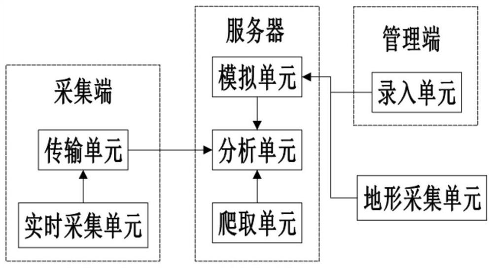
[0050] Such as figure 1 As shown, the point selection system for tunnel risk monitoring includes terrain acquisition unit, simulation unit, input unit, crawling unit, analysis unit, real-time acquisition unit and transmission unit. Wherein, the crawling unit, the simulation unit and the analysis unit are integrated in the server. In this embodiment, the server is a Tencent Cloud server; the real-time acquisition unit and the transmission unit are integrated in the acquisition end. The input unit is integrated in the management terminal, and the management terminal is a smart phone loaded with the corresponding APP. The terrain acquisition unit is a 3D laser scanner.

[0051] The terrain acquisition unit is used to collect terrain data inside and outside the tunnel, and the simulation unit is used to perform BIM modeling based on the terrain data to obtain the tunnel basic model; the input unit is used to input tunnel survey data and update the slope survey data , survey data...

Embodiment 2

[0057] The difference between this embodiment and Embodiment 1 is that there are many tunnels in this embodiment, and each tunnel has its own acquisition unit and transmission unit, and each transmission unit has a unique number; it also includes a storage unit, which stores There are geographical locations of tunnels corresponding to each numbered transmission unit; the storage unit is integrated on the server.

[0058] The acquisition unit includes vibration sensors, cameras and pickups set at the basic monitoring points; when the monitoring value of a certain tunnel vibration sensor exceeds the preset value, the corresponding transmission unit sends an abnormal vibration signal to the server and communicates with the server in real time; the server receives After the abnormal vibration signal, according to the geographic location information of each tunnel, an emergency signal is sent to the transmission unit of the tunnel within the preset distance of the tunnel; the transm...


PUM


Abstract

The invention belongs to the technical field of tunnel monitoring, and particularly relates to a point location selection method and system for tunnel risk monitoring, and the system comprises a terrain collection unit, a simulation unit, an input unit, an analysis unit and a real-time collection unit. The terrain acquisition unit is used for acquiring terrain data inside and outside a tunnel, and the simulation unit is used for performing BIM modeling according to the terrain data to obtain a tunnel basic model; the input unit is used for inputting survey data of a tunnel, and the survey data comprises geological survey data, geophysical prospecting data, drilling data and surveying and mapping data; the simulation unit is also used for combining the survey data with the tunnel basic model to obtain a tunnel simulation model; and the analysis unit is used for performing regional analysis and point location analysis on the tunnel simulation model, obtaining a basic monitoring point location according to the point location analysis, obtaining a special monitoring region according to the regional analysis, and obtaining a special monitoring point location. According to the invention, a proper tunnel monitoring point position can be selected.

Description

technical field [0001] The invention belongs to the technical field of tunnel monitoring, in particular to a point selection method and system for tunnel risk monitoring. Background technique [0002] Tunnel is a kind of traffic road dug through the mountain, and it is a form of human use of the inner space of the mountain. Reasonable development of tunnels can provide great convenience for people's travel. However, once a safety accident occurs and is not handled properly, it will cause very serious consequences. [0003] The mainstream tunnel monitoring technology mainly obtains the displacement and earth pressure at the tunnel monitoring point by arranging various sensors and mechanical facilities, and infers the state of the tunnel by changing the corresponding parameters. Because the consequences of tunnel risks are very serious, in order to ensure the effectiveness of monitoring results, the selection of monitoring points is very important. [0004] At present, moni...

Claims


Application Information

Patent Timeline
Patent Type & Authority Applications(China)
IPC IPC(8): G06Q10/06G06Q50/26G06F30/20G06K9/00G16Y10/40G16Y20/10G16Y20/20G16Y40/10G01H17/00G01V1/20G01D21/02E21F17/00E21F17/18
CPCG06Q10/0635G06Q50/265G06F30/20G16Y10/40G16Y20/10G16Y20/20G16Y40/10G16Y40/20G16Y40/50G01H17/00G01V1/20G01D21/02E21F17/00E21F17/18G06V20/54Y02A90/10
Inventor 王圣龙赵智辉杨金虎陈贵川闫国才颜恭彬
Owner CHINA COAL TECH & ENG GRP CHONGQING RES INST CO LTD
Why Eureka
Try Eureka