GIP driving circuit of low-power-consumption display screen and control method of GIP driving circuit

A technology of drive circuit and control method, which is applied in static indicators, instruments, etc., can solve the problems of high power consumption and reduced battery life, and achieve the effects of reducing power consumption, improving battery life and service life

Pending Publication Date: 2021-05-25
FUJIAN HUAJIACAI CO LTD
View PDF0 Cites 1 Cited by
  • Summary
  • Abstract
  • Description
  • Claims
  • Application Information

AI Technical Summary

Problems solved by technology

However, higher resolution means higher power consumption for the display screen, which reduces battery life

Method used


Image

  • GIP driving circuit of low-power-consumption display screen and control method of GIP driving circuit
  • GIP driving circuit of low-power-consumption display screen and control method of GIP driving circuit
  • GIP driving circuit of low-power-consumption display screen and control method of GIP driving circuit

Examples


Embodiment 1

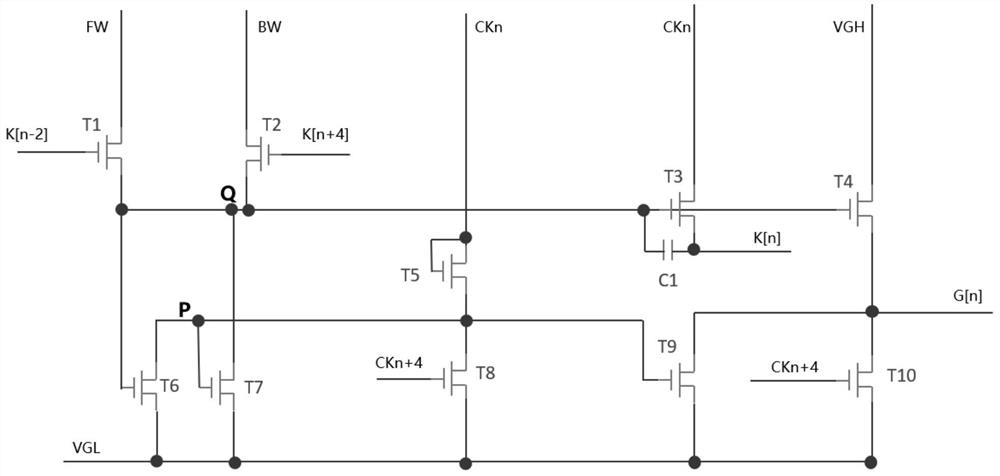
[0039] Please refer to figure 1 and image 3 , Embodiment 1 of the present invention is:

[0040] Please refer to figure 1, a GIP driving circuit of a low-power display screen, comprising a transistor T1, a transistor T2, a transistor T3, a transistor T4, a transistor T5, a transistor T6, a transistor T7, a transistor T8, a transistor T9, a transistor T10 and a capacitor C1, the transistor The source of T1 is electrically connected to the gate of transistor T6, the drain of transistor T7, the source of transistor T2, the gate of transistor T3 and one end of capacitor C1 respectively, and the drain of said transistor T6 is respectively connected to the gate of transistor T7. Pole, the drain of transistor T8, the source of transistor T5 and the gate of transistor T9 are electrically connected, and the drain of transistor T9 is electrically connected with the drain of transistor T10 and the source of transistor T4 respectively and the drain of transistor T9 1. The drain of the...

Embodiment 2

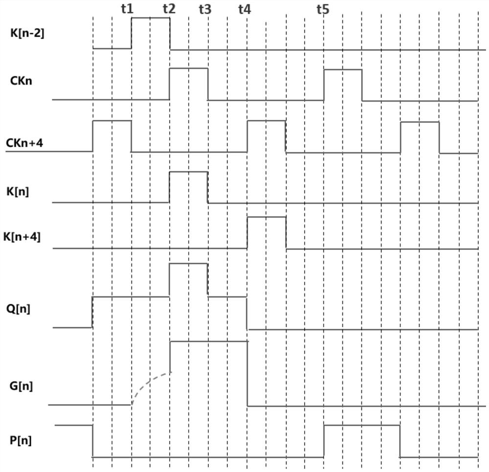
[0053] Please refer to Figure 1 to Figure 3 , the second embodiment of the present invention is:

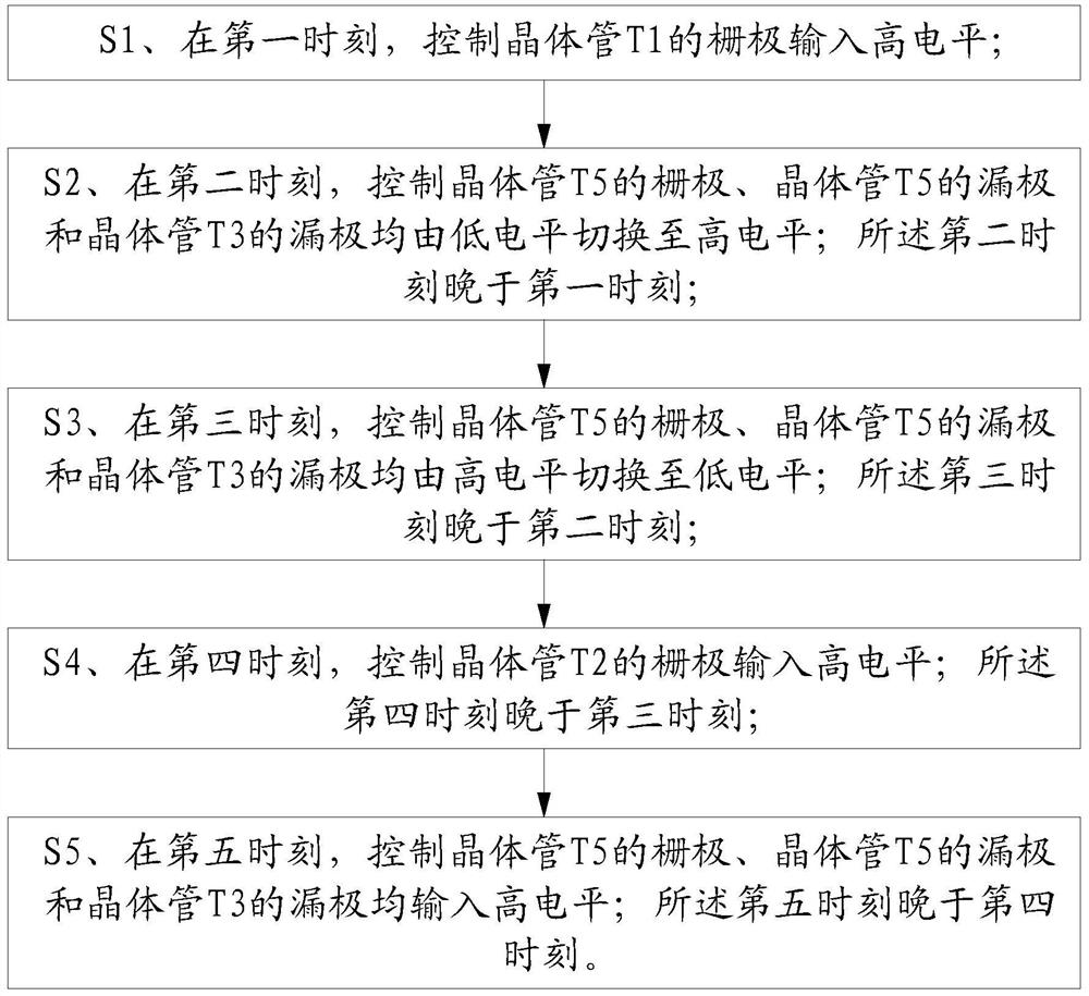
[0054] Please refer to figure 2 , a control method for a GIP drive circuit of a low-power display screen, comprising the following steps:

[0055] S1. At the first moment, control the gate of the transistor T1 to input a high level;

[0056] S2. At a second moment, control the gate of the transistor T5, the drain of the transistor T5, and the drain of the transistor T3 to switch from a low level to a high level; the second moment is later than the first moment;

[0057] S3. At a third moment, control the gate of the transistor T5, the drain of the transistor T5, and the drain of the transistor T3 to switch from a high level to a low level; the third moment is later than the second moment;

[0058] S4. At the fourth moment, the gate of the control transistor T2 inputs a high level; the fourth moment is later than the third moment;

[0059] S5. At a fifth moment, control the ...


PUM


Abstract

The invention relates to the technical field of GIP driving circuits, in particular to a GIP driving circuit of a low-power-consumption display screen and a control method of the GIP driving circuit, which comprises a transistor T1, a transistor T2, a transistor T3, a transistor T4, a transistor T5, a transistor T6, a transistor T7, a transistor T8, a transistor T9, a transistor T10 and a capacitor C1, a source electrode of a transistor T1 is electrically connected with a grid electrode of a transistor T6, a drain electrode of a transistor T7, a source electrode of a transistor T2, a grid electrode of a transistor T3 and one end of a capacitor C1, a drain electrode of a transistor T9 is electrically connected with a drain electrode of a transistor T10 and a source electrode of a transistor T4, and the drain electrode of the transistor T9, the drain electrode of the transistor T10 and the source electrode of the transistor T4 are all connected with grid electrode wires. Therefore, the drain end of the transistor T4 can be connected to a direct-current voltage level, the power consumption of a display screen can be effectively reduced, and the endurance time and the service life of display equipment are prolonged.

Description

technical field [0001] The invention relates to the technical field of GIP driving circuits, in particular to a GIP driving circuit of a display screen with low power consumption and a control method thereof. Background technique [0002] With the continuous development of the information society, people's demand for high-resolution display screens continues to increase, and higher resolution at the same size often represents a more delicate display screen. However, higher resolution means higher power consumption for the display screen, which reduces battery life. Contents of the invention [0003] The technical problem to be solved by the present invention is: to provide a GIP driving circuit of a display screen with low power consumption and its control method, which can effectively reduce the power consumption of the GIP driving circuit of the display screen and improve the battery life and service life of the display device. [0004] In order to solve the problems of...

Claims


Application Information

Patent Timeline
IPC IPC(8): G09G3/20
CPCG09G3/20G09G2330/021
Inventor 谢建峰
Owner FUJIAN HUAJIACAI CO LTD
Why Eureka
Try Eureka