Automatic stapling and handle mounting device
A stapling and automatic technology, applied in brushes, household appliances, applications, etc., can solve the problems of affecting production efficiency, low success rate, single-sided nailing of the nailing device, etc., so as to improve the success rate of assembly and reduce production costs. , Reasonable effect of structural design
- Summary
- Abstract
- Description
- Claims
- Application Information
AI Technical Summary
Problems solved by technology
Method used
Image

Examples
Embodiment 1
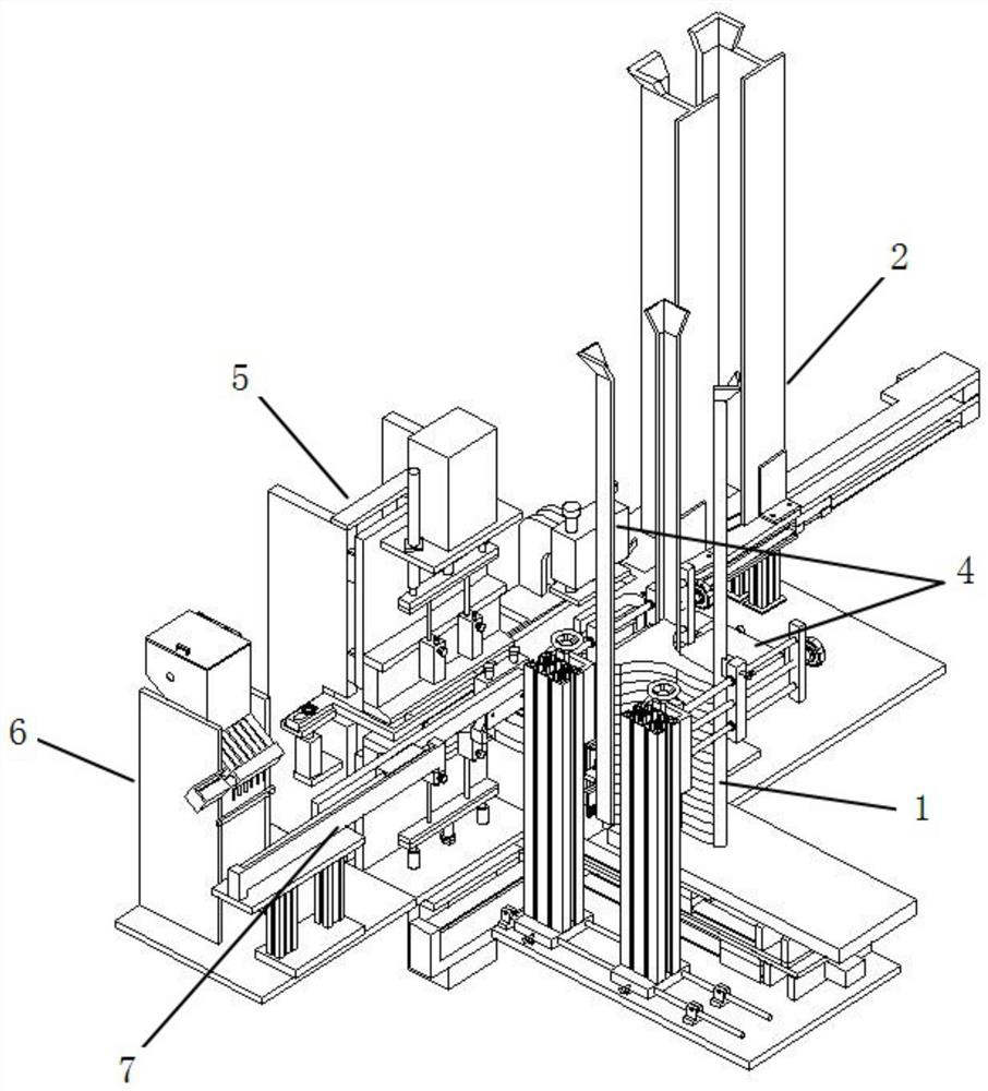
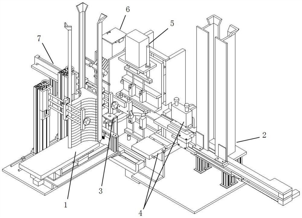
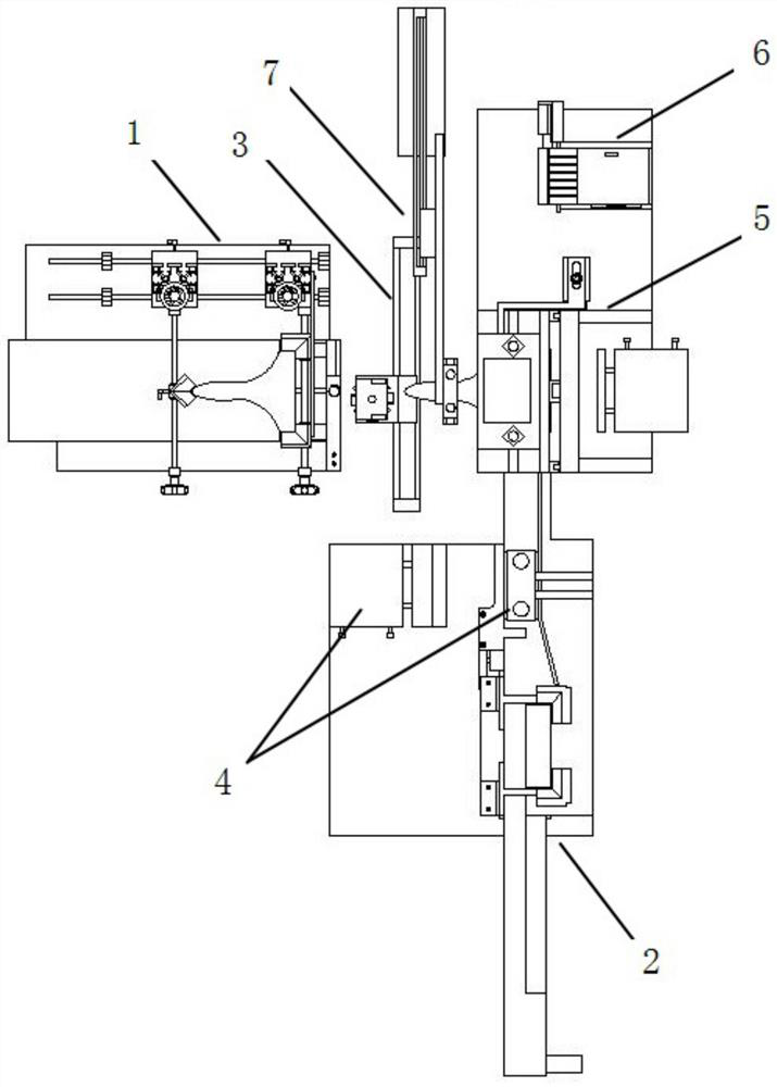
[0051] This embodiment is a kind of automatic stapling handle device, such as Figure 1-3 As shown, it includes brush handle feeding device 1, brush head feeding device 2, brush handle edge trimming device 3, brush head pre-supporting device 4 and nailing device 5, between brush handle feeding device 3 and nailing device 5 A brush handle trimming device 3 for trimming the head of the brush handle 801 is provided on the transmission line, and a brush handle trimming device 3 for trimming the metal sleeve in the brush head is provided on the transmission line between the brush head feeding device 2 and the nailing device 5. 802 is a brush head pre-supporting device 4 for pre-supporting.
[0052] like Figure 4-8 As shown, the brush handle feeding device 2 includes a first base 101 , a first reciprocating linear drive mechanism 102 , a first movable plate 103 , a second reciprocating linear drive mechanism 104 , a second movable plate 105 and a brush handle storage rack. The up...
Embodiment 2
[0065] In this embodiment, the automatic stapling and handling device also includes a nail feeding device 6 for delivering nails 804 to the nailing device, such as Figure 19-20 As shown, the nail feeding device 6 includes a second support 601, a storage box 602, a blanking plate 603, a trough 604, a turning shaft 605, a flexible dial 606, a second rotating motor 607, a feeding box 608, and a feeding tube 609 and the air pump 610, the upper part of the second support 601 is fixed with a material storage box 602, the bottom of the material storage box 602 is provided with a blanking plate 603 arranged obliquely, and the upper end of the blanking plate 603 is provided with a number of troughs 604 inwards , and the width of the trough 604 is equal to the outer diameter of the shank of the nail 804 , and the width of the trough 604 is smaller than the outer diameter of the head of the nail 804 . The inner rotation support of the material storage box 602 is provided with a material...
Embodiment 3
[0067] In this embodiment, the automatic stapling handle device also includes a discharge device 7 for transferring finished products, such as Figure 21 As shown, the unloading device 7 includes a third support 701, a sixth reciprocating linear drive mechanism 702, a fifth movable plate 703, and a mechanical gripper 704. The sixth reciprocating linear drive mechanism 702, the outer end of the fifth movable plate 703 is equipped with a mechanical gripper 704 capable of grabbing the brush handle 801, and the mechanical gripper 704 is an electric gripper or a pneumatic gripper.
PUM
 Abstract
Description
Claims
Application Information
 - R&D
- Intellectual Property
- Life Sciences
- Materials
- Tech Scout
- Unparalleled Data Quality
- Higher Quality Content
- 60% Fewer Hallucinations
Browse by: Latest US Patents, China's latest patents, Technical Efficacy Thesaurus, Application Domain, Technology Topic, Popular Technical Reports.
© 2025 PatSnap. All rights reserved.Legal|Privacy policy|Modern Slavery Act Transparency Statement|Sitemap|About US| Contact US: help@patsnap.com