
Patsnap Eureka
For R&D, Patsnap Eureka makes reading and utilizing patents & technical documents easy.
Patsnap Eureka AIR
Designed for self-driven R&D workflows. Generate viable solutions, solve complex R&D challenges, empower your innovation with AI.

Patsnap Eureka Materials
Designed for material experts only. Revolutionize your material R&D, from search, analyze, to developing new materials.

TechResearch
Generate reliable direction feasibility study reports for your R&D in just a few steps.

TechSeek
Discover and master advanced knowledge NOW. Basics, ideas, possibilities, all at once.

TechMind
As an expert in R&D Theories, TechMind can generates customized viable solutions instantly.

TechRisk
Analyze your overall solution with one click, know your potential R&D risks in advance.

TechMonitor
Get weekly tech updates, stay abreast of the latest tech innovations and key insights.
CBCT acquisition device and acquisition method for animals with different body types
A collection device and animal technology, which is applied in the fields of radiological diagnostic equipment, medical science, and radiation generation arrangement, etc., can solve the problems that the detection plate cannot fully exert the detection accuracy, the size cannot be achieved, and the matching can achieve scanning image information rich effect
- Summary
- Abstract
- Description
- Claims
- Application Information
AI Technical Summary
Problems solved by technology
Method used
Image

Examples
Embodiment 1
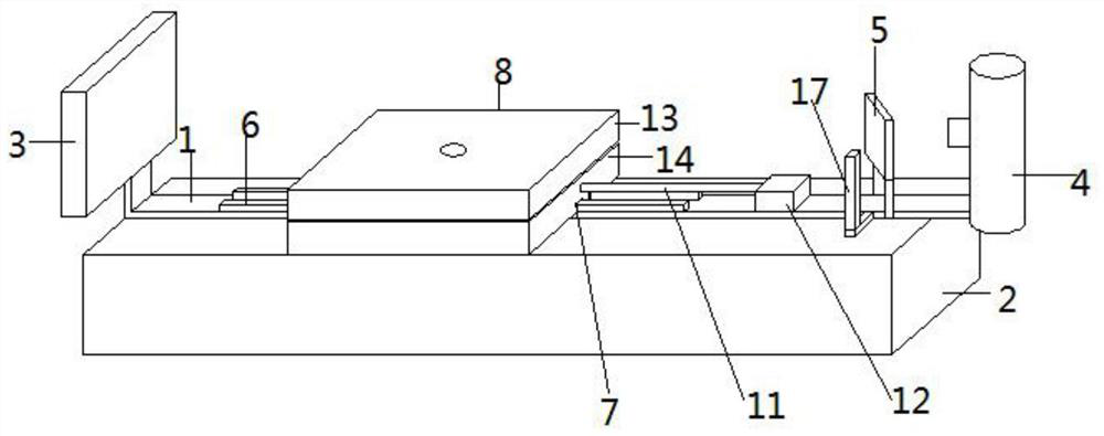
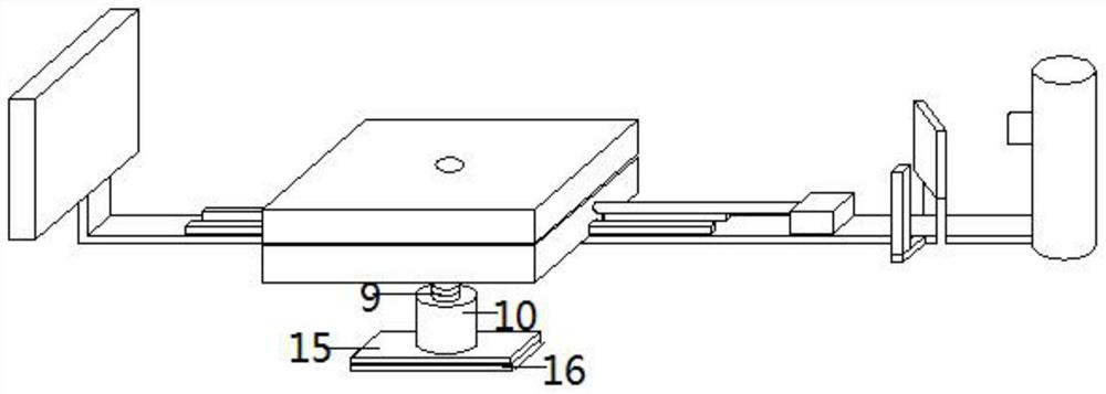
[0019] Such as figure 1 and figure 2 The shown CBCT acquisition device for animals of different sizes includes a guide rail 1, a support frame 2 is provided under the guide rail 1, and a flat panel detector 3 and an X-ray tube 4 are respectively installed at both ends of the guide rail 1, The front side of the X-ray tube 4 is provided with a reflective film 5, the plane where the reflective film 5 is located has an included angle of 45° with the ray direction of the X-ray tube 4, and an LED lamp is provided on one side of the reflective film 5. Source 17, the light source direction of the LED light source 17 is perpendicular to the ray direction of the X-ray tube 4, the reflective film 5 and the LED light source 17 are connected to the guide rail through a bracket, the guide rail 1 is provided with a slider 6, The slider 6 is slidably connected to the chute 7, the chute 7 is opened at the bottom of the detection table 8, the bottom of the detection table 8 is connected to th...
Embodiment 2
[0021] Such as figure 1 and figure 2 The shown CBCT acquisition device for animals of different sizes includes a guide rail 1, a support frame 2 is provided under the guide rail 1, and a flat panel detector 3 and an X-ray tube 4 are respectively installed at both ends of the guide rail 1, The front side of the X-ray tube 4 is provided with a reflective film 5, the plane where the reflective film 5 is located has an included angle of 45° with the ray direction of the X-ray tube 4, and an LED lamp is provided on one side of the reflective film 5. Source 17, the light source direction of the LED light source 17 is perpendicular to the ray direction of the X-ray tube 4, the reflective film 5 and the LED light source 17 are connected to the guide rail through a bracket, the guide rail 1 is provided with a slider 6, The slider 6 is slidably connected to the chute 7, the chute 7 is opened at the bottom of the detection table 8, the bottom of the detection table 8 is connected to th...
PUM
 Abstract
Description
Claims
Application Information
 - R&D Engineer
- R&D Manager
- IP Professional
- Industry Leading Data Capabilities
- Powerful AI technology
- Patent DNA Extraction
Browse by: Latest US Patents, China's latest patents, Technical Efficacy Thesaurus, Application Domain, Technology Topic, Popular Technical Reports.
© 2024 PatSnap. All rights reserved.Legal|Privacy policy|Modern Slavery Act Transparency Statement|Sitemap|About US| Contact US: help@patsnap.com