Remote pressure transmission system for gas fire extinguishing equipment

A technology of remote transmission and fire extinguishing equipment, which is applied in the field of gas fire extinguishing equipment pressure remote transmission system, which can solve fire safety problems, gas shortage, gas loss and other problems, and achieve the effect of ensuring fire safety, normal operation and gas filling

Inactive Publication Date: 2021-05-28
湖南省金鼎消防器材有限公司
View PDF7 Cites 0 Cited by
  • Summary
  • Abstract
  • Description
  • Claims
  • Application Information

AI Technical Summary

Problems solved by technology

[0005] The purpose of the present invention is to provide a gas fire extinguishing equipment pressure remote transmission system to solve the problem that most of the existing gas fire extinguishing devices proposed in the above-mentioned background technology have a single working gas tank, and the working gas tank is filled with carbon dioxide or other Some inert gases with fire extinguishing function, when a fire breaks out, the working gas tank releases the gas, and the oxygen in the air is eliminated through the gas, so as to play the role of fire extinguishing. However, during the normal storage process of the working gas tank, the working gas tank The gas will be lost. When a fire occurs, due to the lack of gas in the working gas tank, the spread of the fire cannot be effectively prevented, causing serious fire safety problems.

Method used


Image

  • Remote pressure transmission system for gas fire extinguishing equipment
  • Remote pressure transmission system for gas fire extinguishing equipment
  • Remote pressure transmission system for gas fire extinguishing equipment

Examples


Embodiment Construction

[0030] The technical solutions in the embodiments of the present invention will be clearly and completely described below with reference to the accompanying drawings in the embodiments of the present invention. Obviously, the described embodiments are only a part of the embodiments of the present invention, but not all of the embodiments. Based on the embodiments of the present invention, all other embodiments obtained by those of ordinary skill in the art without creative efforts shall fall within the protection scope of the present invention.

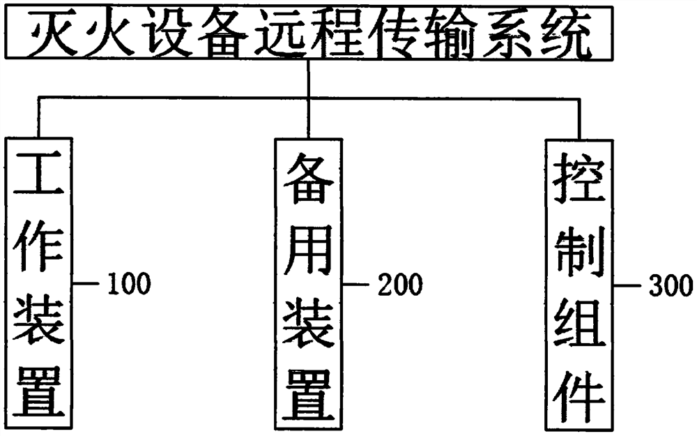
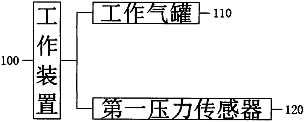
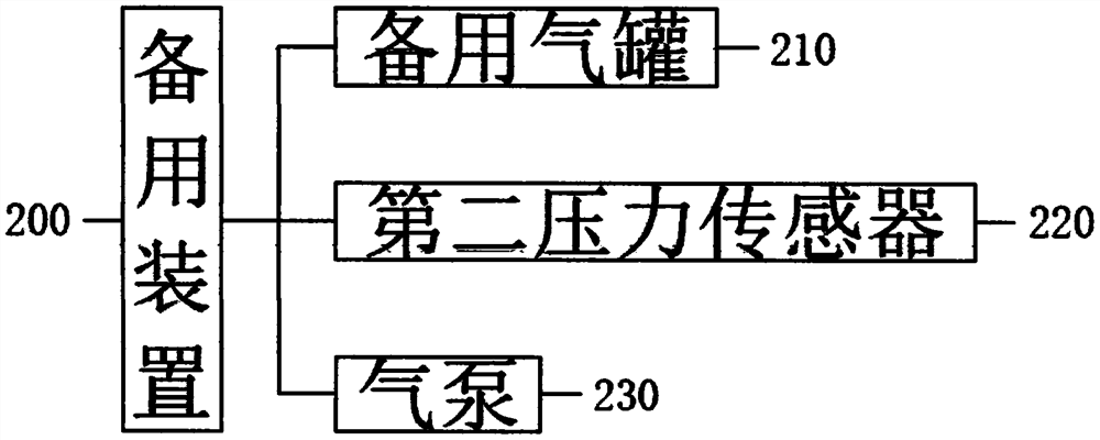
[0031] The invention provides a pressure remote transmission system for gas fire-extinguishing equipment, which adds a spare gas tank to replenish the working gas tank in real time, and can timely replace the exhausted standby tank through the remote transmission system, and can always keep the working gas tank. The filling of gas ensures fire safety, please refer to figure 1 , the working device 100, the standby device 200 and the co...


PUM


Abstract

The invention discloses a remote pressure transmission system for gas fire-extinguishing equipment in the technical field of fire-fighting equipment. The remote pressure transmission system comprises a working device, a standby device, a control assembly, a first pressure sensor, a second pressure sensor and an air pump; the standby device is connected with the working device; the control assembly is respectively connected with the working device and the standby device, and the working device comprises a working gas tank; the first pressure sensor is mounted on the working gas tank, and the standby device comprises a standby gas tank; the second pressure sensor is mounted on the standby gas tank; and an air inlet of the air pump is arranged on an air outlet of the standby air tank through a pipeline, According to the remote pressure transmission system, the standby gas tank is added to supplement gas to the working gas tank in real time, and the standby gas tank with gas out can be replaced in time through the remote transmission system, so that the gas filling of the working gas tank can be always kept, and the fire safety is ensured.

Description

technical field [0001] The invention relates to the technical field of fire-fighting facilities, in particular to a remote pressure transmission system for gas fire-extinguishing equipment. Background technique [0002] Firefighting Device refers to the automatic fire alarm system, indoor fire hydrant, outdoor fire hydrant, and other fixed facilities in the building. Automatic fire protection facilities are divided into automatic facilities for electrical systems and automatic facilities for water systems. Electrical fire safety inspection is based on modern physical phenomena such as thermal radiation, acoustic emission, and electromagnetic emission during the operation of electrical facilities, using internationally advanced high-tech instruments and equipment, combined with traditional inspection methods to carry out all-round quantitative monitoring of electrical facilities . In order to more comprehensively, scientifically and accurately reflect the existence, degree ...

Claims


Application Information

Patent Timeline
Patent Type & Authority Applications(China)
IPC IPC(8): A62C35/02A62C37/50A62C31/00
CPCA62C31/00A62C35/02A62C37/50
Inventor 杨继才龙荣范胜孙秧青何斌陈瑶
Owner 湖南省金鼎消防器材有限公司
Why Eureka
Try Eureka