Ore pass dust treatment device

A technology for dust treatment and sliding mines, which is applied in the direction of combined devices, separation of dispersed particles, chemical instruments and methods, etc. It can solve the problems of inefficient dust treatment, affecting the normal operation of staff, and excessive dust in shafts.

Inactive Publication Date: 2021-05-28
凌源日兴矿业有限公司
View PDF6 Cites 0 Cited by
  • Summary
  • Abstract
  • Description
  • Claims
  • Application Information

AI Technical Summary

Problems solved by technology

During the process of lowering the ore in the mine shaft, due to the movement of the airflow, the dust on the upper side of the loading vehicle will be raised, resulting in more dust in the shaft, which will affect the normal operation of the staff
[0003] Existing mine shafts mostly use exhaust fans to deal with the dust generated during the ore lowering process, but this dust treatment method has high requirements for exhaust channels, and when the depth of the mine shaft is deep, It is not efficient to deal with dust through exhaust, and it is necessary to set up a deep exhaust channel, which will increase the construction cost of the mine shaft

Method used


Image

  • Ore pass dust treatment device
  • Ore pass dust treatment device
  • Ore pass dust treatment device

Examples


Embodiment 1

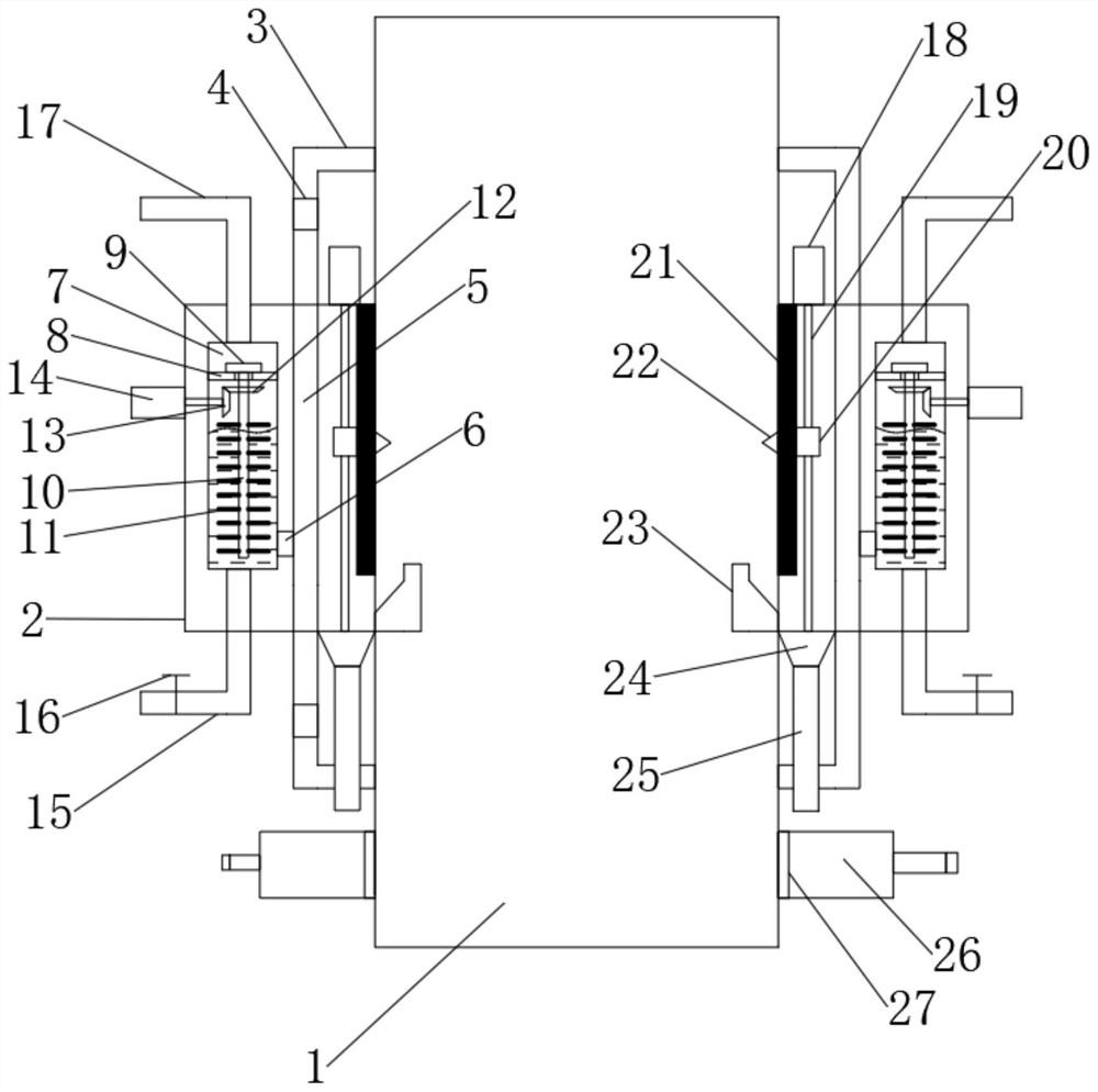
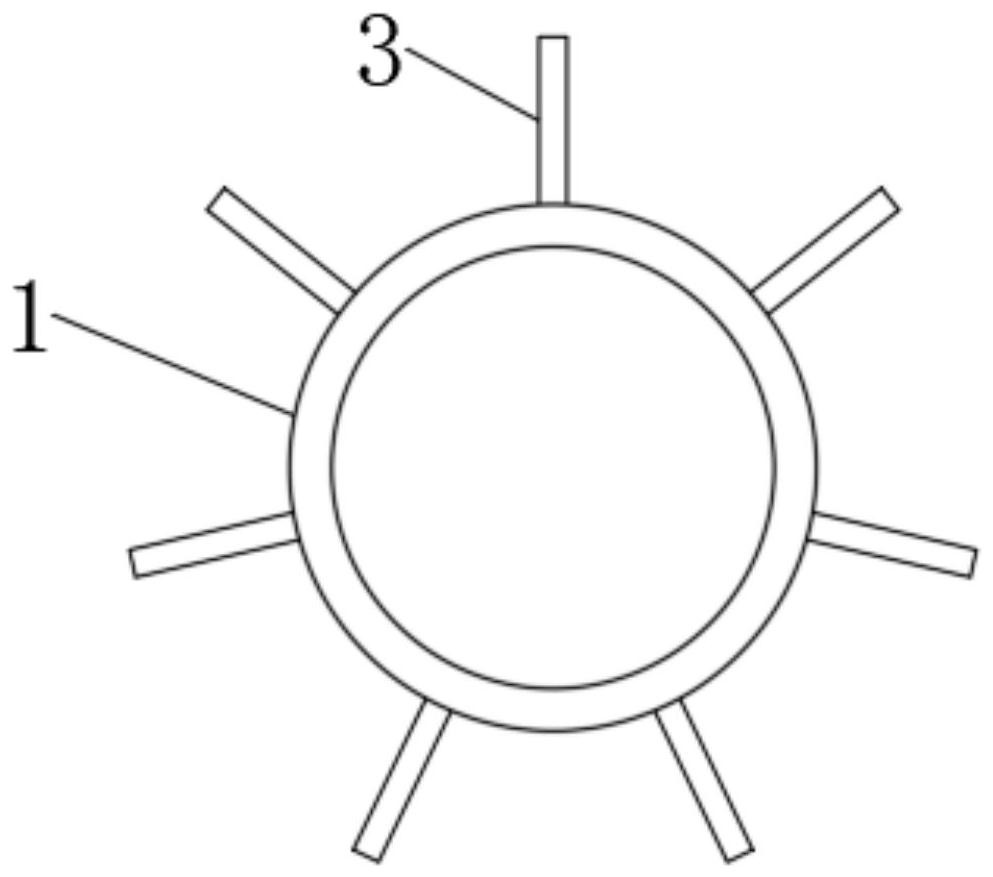
[0026]Such asFigure 1-4As shown, a slip dust treatment apparatus includes a mounting tank 2 mounted on the side of the mine 1, and the upper side of the mounting tank 2 is provided with a suction tube 3, and the upper straw 3 is evenly distributed around the outer periphery of the mine 1. The suction pump 4 is provided in the upper suction tube 3, and the upper strip 3 is connected to the air tube 5, the air pipe 5 is connected to the joint pipe 6, and the engaging tube 6 is connected to the filter cartridge 7, the filter cartridge The cleaning liquid is provided, and the filter cartridge 7 is provided with a stirring device, and the bottom of the filter cartridge 7 is provided with a drain pipe 15, and a valve 16 is provided on the drain pipe 15, the upper side of the filter cartridge 7. An air intake pipe 17 is provided, and the mounting tank 2 is provided with an electrostatic adsorption plate 21 between 1, and the electrostatic adsorption plate 21 is provided with a scraper blad...

Embodiment 2

[0039]The present embodiment is a further improvement and definition of Example 1 on the basis of Example 1.

[0040]A slip dust treatment apparatus, including all components in Example 1, further comprising:

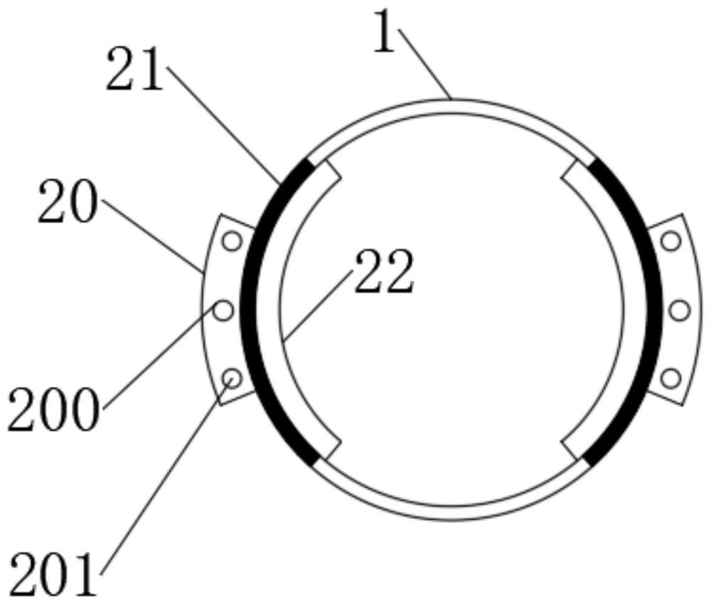
[0041]Further, the lifting device includes a second motor 18 that is fixed to the mounting tank 2, the second motor 18 is connected to the threaded rod 19, and the intermediate position of the rumor block 20 is provided with a threaded hole. 200, the threaded hole 200 is threaded with the threaded rod 19, and a light pore 201 is provided on the lift block 20, which is provided with a slip post, and the spool is fixed to the mounting box 2.

[0042]Specifically, by setting the second motor 18 and the threaded rod 19, the lifting control of the lifting block 20 is realized, so that the upper and lower moving movement of the electrostatic adsorption plate 21 is moved, and the dust removal operation is performed.

[0043]Further, two light pores 201 are provided.

[0044]Specifically, in order ...


PUM


Abstract

The invention discloses an ore pass dust treatment device, relates to the technical field of ore pass dust treatment, and mainly solves the problem that the existing ore pass dust cleaning cost is relatively high. The device comprises an installation box installed on the side edge of a mine; wherein upper suction pipes are arranged on the upper side of the installation box and evenly distributed on the periphery of the mine, suction pumps are arranged in the upper suction pipes, the upper suction pipes are connected with an air guide pipe, the air guide pipe is connected with a confluence pipe, and the confluence pipe is connected with a filter cartridge. A stirring device is arranged in the filter cartridge, an electrostatic adsorption plate is arranged between the mounting box and the mine, a scraping plate is arranged on the electrostatic adsorption plate, a magnet is arranged on the scraping plate, a lifting block is arranged on the outer side of the electrostatic adsorption plate, and the lifting block is connected with a lifting device and is an iron block. A guide groove is formed in the bottom of the mine, a funnel groove is formed in the bottom of the guide groove, and a discharging pipe is arranged at the bottom of the funnel groove.

Description

Technical field[0001]The present invention relates to the field of slipping dust treatment technology, and is specifically a slip dust treatment device.Background technique[0002]The slipping mine is to use the ore of the upper middle section to put the wellbore passed by the self-weight to the lower transport roadway. In the process of carrying out the ore, the dust is moved from the airflow, so that dust on the upper side of the charge vehicle has caused more dust in the wellbore, affecting the normal operation of the staff.[0003]Most of the dust treatment methods produced during the ore lowering process are dredies through the exhaust fan, but this dust treatment is higher for the exhaust passage, and when the depth of the slip is deep, Treating dust from exhausting is not efficient, requiring a deeper exhaust passage, increasing additional slip well construction costs.Inventive content[0004]It is an object of the embodiment of the present invention to provide a slip dust treatmen...

Claims


Application Information

Patent Timeline
Patent Type & Authority Applications(China)
IPC IPC(8): B01D50/00
CPCB01D50/00
Inventor 张文国郗广奇解本德王成武耀健刘国志吕长东
Owner 凌源日兴矿业有限公司
Why Eureka
Try Eureka