
FP type chip pin forming device and forming method

A technology of chip tubes and pins, which is applied in the field of FP-type chip pin forming devices, can solve the problems of chip damage, static electricity, sparking, etc., and achieve the effect of ensuring physical damage and electrostatic damage

Pending Publication Date: 2021-05-28
大连长丰实业总公司
View PDF0 Cites 1 Cited by
  • Summary
  • Abstract
  • Description
  • Claims
  • Application Information

AI Technical Summary

Problems solved by technology

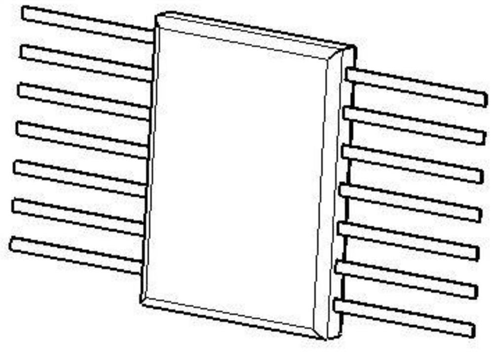
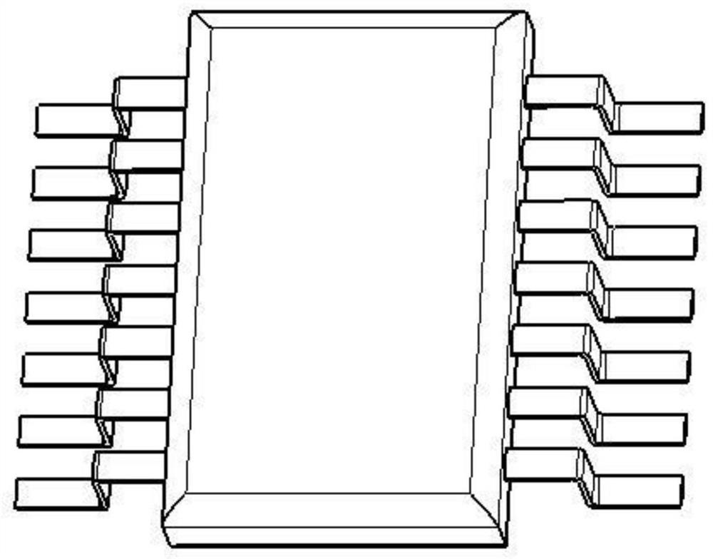
[0003] If it is applied to FP chips, it is necessary to shape the pins. In the prior art, tweezers are used to manually bend and shape the chip pins, but there are the following problems: 1. When bending and forming manually, there is no fixing measure for the shoulder of the chip. , resulting in stress on the root of the chip pins during the forming process, and there is a risk of cracking; 2. Bending the chip pins with tweezers is a hard contact between metal and metal, which can easily cause physical damage to the chip pins, and It is easy to generate static electricity and damage the chip; 3. Since the rebound of the chip lead cannot be controlled by manual bending, it will cause the chip pins to be lifted or not coplanar after forming, and the solder joints are prone to cracking after chip welding and environmental testing; 4. Process parameters such as pin forming shoulder width, standing height, and welding surface length are controlled, and the above parameters are manually controlled by the operator, which is difficult; 5. Manual bending and forming can also easily cause chip pins The lateral displacement makes the spacing between the pins of the chip uneven. Since the spacing between the pins of the chip itself is small, if the chip with the uneven spacing of the pins is soldered to the PCB, there will be false soldering and false soldering. and other phenomena, causing problems such as short circuit, leakage, ignition, etc., which will have a negative impact on product quality

Method used


Image

  • FP type chip pin forming device and forming method
  • FP type chip pin forming device and forming method
  • FP type chip pin forming device and forming method

Examples


Embodiment Construction

[0029] According to the attached Figure 1-5 The forming device of the present invention is introduced in detail. The forming device includes a clamping device, an upper mold 4 and a lower mold 1, wherein the lower mold 1 includes a bottom plate, two first raised ribs 2 and a raised line 3, and the raised line 3 is located in the center of the bottom plate. Two first convex ribs 2 are symmetrically distributed on both sides of the convex strip 3, wherein the heights of the first convex rib 2, the convex strip 3 and the bottom plate are successively reduced; correspondingly, the upper mold 4 includes a top plate, two first flanges 5 and two The second flange 6, the height of the top plate, the two first flanges 5 and the two second flanges 6 are raised successively, wherein the two first flanges 5 and the two second flanges 6 are about the central axis of the top plate Symmetrical distribution.

[0030] The first flange 5 of the upper mold 4 corresponds to the position of the ...


PUM


Abstract

The invention relates to an FP type chip pin forming device and a forming method. The device comprises a clamping device, an upper die and a lower die; the lower die comprises a bottom plate, two first convex ribs and a convex strip, the convex strip is located in the center of the bottom plate, and the two first convex ribs are symmetrically distributed on the two sides of the convex strip; the upper die comprises a top plate, two first flanges and two second flanges, and the two first flanges and the two second flanges are symmetrically distributed with respect to the central axis of the top plate; the heights of the first convex ribs, the convex strip and the bottom plate of the lower die are sequentially decreased; and the heights of the top plate, the two first flanges and the two second flanges of the upper die are sequentially increased. According to the FP type chip pin forming device and the forming method, the forming mode is one-time forming, so that the lateral displacement of a chip pin caused by repeated bending when the chip pin is bent by tweezers is avoided.

Description

technical field [0001] The invention belongs to the field of chip packaging, and in particular relates to an FP-type chip pin forming device and a forming method. Background technique [0002] In recent years, with the rapid development of electronic technology, the types of packaging of chips inside airborne electronic products are increasing. During the repair process of products, the welding problem of special packaging chips has gradually become a factor affecting product quality. Many types of chips, especially FP chips, have not been pin-shaped when they leave the factory. Users need to manually bend them to shape the pins. The main purpose of chip pin forming is to ensure that the chip pins can be soldered to the PCB phase. On the corresponding pad; on the other hand, it mainly solves the problem of stress release. After the electronic components are welded, they can meet the environmental stress of the product, and part of the stress is eliminated. The stress relief ...

Claims


Application Information

Patent Timeline
Patent Type & Authority Applications(China)
IPC IPC(8): B21F1/00B21F11/00
CPCB21F1/004B21F11/00
Inventor 金萍魏创波单彬
Owner 大连长丰实业总公司
Learn More