Bar and pipe cutting treatment device for building material machining

A processing device and rod material technology, which is applied in the field of bar and pipe material cutting and processing devices for building materials processing, can solve the problems of unguaranteed size, danger, time-consuming and laborious, etc.

Inactive Publication Date: 2021-05-28
哈尔滨市阿城区胜达建筑材料厂
View PDF0 Cites 0 Cited by
  • Summary
  • Abstract
  • Description
  • Claims
  • Application Information

AI Technical Summary

Problems solved by technology

[0002] In the building material market, bars or pipes are mostly standard sizes, which are not only convenient for sale but also convenient for finishing. However, standard length bars and pipes cannot be processed without cutting. Most old-fashioned bars and pipes are cut by band sawing or cutting. Workers hold cutting saws for cutting. Using cutting saws is not only dangerous but also cannot guarantee the size, and the work efficiency is also very low. However, when cutting with band sawing machines, it is necessary to fix and mark the size of the bar or pipe every time it is cut, which is not only time-consuming and laborious.

Method used


Image

  • Bar and pipe cutting treatment device for building material machining
  • Bar and pipe cutting treatment device for building material machining
  • Bar and pipe cutting treatment device for building material machining

Examples


specific Embodiment approach 1

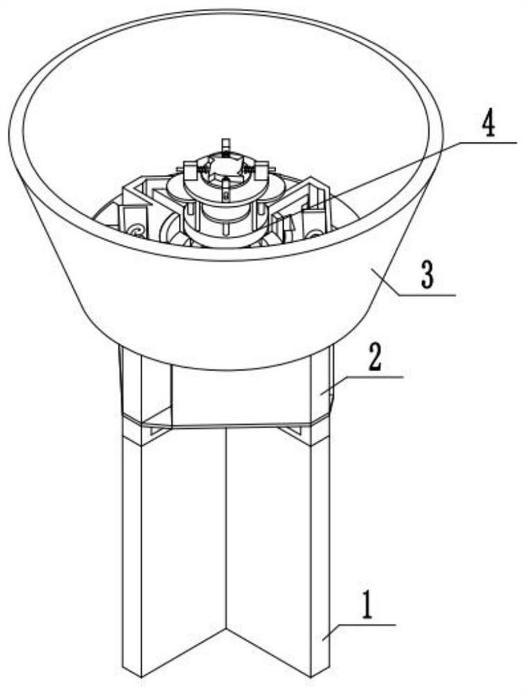
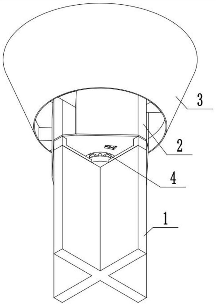
[0036] Combine below figure 1 , 2Description of this embodiment, a bar and pipe cutting processing device for building materials processing, including a fixed cross base 1, a storage and feeding device 2, a leftover material collection device 3 and a cutting processing device 4, and the top of the cross base 1 is fixedly installed with The cutting processing device 4 is provided with a storage and feeding device 2 , and the scrap collecting device 3 is slidably installed on the cutting processing device 4 .

specific Embodiment approach 2

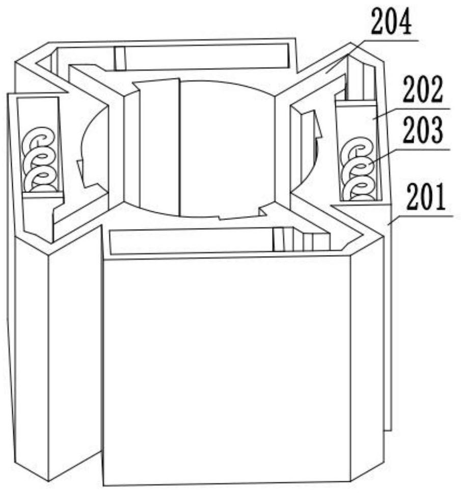
[0038] Combine below image 3 Describe this embodiment, this embodiment will further explain the first embodiment, the storage and feeding device 2 includes a storage sleeve 201, a feed plate 202, a feed spring 203, a feed sleeve 204, the storage sleeve 201 and The feed sleeve body 204 is connected, and the feed sleeve body 204 at the communication position is provided with a slope, the feed plate 202 is slidably installed on the storage sleeve body 201, and the two ends of the feed spring 203 are respectively fixedly installed on the storage sleeve body 201 and the feeding sleeve body 201. On the plate 202, the storage sleeve body 201 is provided with a drop groove, the bar or plate is placed in the storage sleeve body 201, the feed spring 203 pushes the feed plate 202 through its own elasticity, and the feed plate 202 pushes the bar or pipe , so that the bar or pipe enters the feeding sleeve 204 through the inclined surface provided on the feeding sleeve 204, so as to realiz...

specific Embodiment approach 3

[0040] Combine below Figure 4 , 5 Describe this embodiment, this embodiment will further explain Embodiment 1, the leftover material collection device 3 includes a collection sleeve body 301, a sleeve body connection block 302, and a sleeve body connection block 302 is fixedly installed on the collection sleeve body 301, the sleeve body The connecting block 302 is provided with a hydraulic lift, and the cover body connecting block 302 is slidably installed on the storage cover body 201, and the hydraulic lift configured by the cover body connecting block 302 is started, so that the cover body connecting block 302 drives the collection cover body 301 to move upwards to realize Block and collect the scraps that fly out, prevent the scraps from hurting people, and collect the scraps at the same time.


PUM


Abstract

The invention relates to a bar and pipe cutting treatment device, in particular to a bar and pipe cutting treatment device for building material machining. The bar and pipe cutting treatment device comprises a fixing cross-shaped base, a storage feeding device, a leftover material collecting device and a cutting treatment device; and the cutting treatment device is arranged on the upper portion of the cross-shaped base, the storage feeding device is installed on the cutting treatment device, and the leftover material collecting device is installed on the cutting treatment device in a sliding mode. According to the bar and pipe cutting treatment device, bars or pipes can be automatically fed, the bars or the pipes can be prevented from entering the device in the working process, transmission of the device is more stable, and the cut bars can automatically fall out and are convenient to collect; and the device can automatically separate cut leftover materials, prevent the leftover materials from entering the device and causing damage to the device, meanwhile, can collect the leftover materials, prevents the leftover materials from hurting people, and facilitates collection of the leftover materials.

Description

technical field [0001] The invention relates to a bar and pipe cutting device, in particular to a bar and pipe cutting and processing device for building materials processing. Background technique [0002] In the building material market, bars or pipes are mostly standard sizes, which are not only convenient for sale but also convenient for finishing. However, standard length bars and pipes cannot be processed without cutting. Most old-fashioned bars and pipes are cut by band sawing or cutting. Workers hold cutting saws for cutting. Using cutting saws is not only dangerous but also cannot guarantee the size, and the work efficiency is also very low. However, when cutting with band sawing machines, it is necessary to fix and mark the size of the bar or pipe every time it is cut, which is not only time-consuming and laborious. . Contents of the invention [0003] The main technical problem to be solved by the present invention is to provide a bar and pipe cutting device for...

Claims


Application Information

Patent Timeline
Patent Type & Authority Applications(China)
IPC IPC(8): B23D21/04B23D19/00B23D33/02B23Q11/00
CPCB23D19/00B23D21/04B23D33/02B23Q11/0042B23Q11/0078
Inventor 郭铁男
Owner 哈尔滨市阿城区胜达建筑材料厂
Why Eureka
Try Eureka