
Automatic positioning, assembling and machining equipment for copper pipes for production of air conditioner condensers

An air-conditioning condenser, assembly and processing technology, applied in the direction of metal processing equipment, metal processing, manufacturing tools, etc., can solve the problems of reduced productivity, increased labor intensity, increased personnel costs, etc., to reduce personnel costs, speed up productivity, avoid consumption time-consuming effect

Inactive Publication Date: 2021-05-28
温州纽木信息科技有限公司
View PDF0 Cites 0 Cited by
  • Summary
  • Abstract
  • Description
  • Claims
  • Application Information

AI Technical Summary

Problems solved by technology

[0004] The purpose of the present invention is to provide automatic positioning and assembly processing equipment for copper tubes used in the production of air-conditioning condensers, so as to solve the problem in the above-mentioned background technology that in the current condenser assembly process, most of them still rely on the staff to manually insert the U-shaped tubes into the fins. In this way, not only the increase of personnel cost and the increase of labor intensity during operation lead to the gradual decrease of productivity and other problems

Method used


Image

  • Automatic positioning, assembling and machining equipment for copper pipes for production of air conditioner condensers
  • Automatic positioning, assembling and machining equipment for copper pipes for production of air conditioner condensers
  • Automatic positioning, assembling and machining equipment for copper pipes for production of air conditioner condensers

Examples


Embodiment Construction

[0028]The following will clearly and completely describe the technical solutions in the embodiments of the present invention with reference to the accompanying drawings in the embodiments of the present invention. Obviously, the described embodiments are only some, not all, embodiments of the present invention. Based on the embodiments of the present invention, all other embodiments obtained by persons of ordinary skill in the art without creative efforts fall within the protection scope of the present invention.

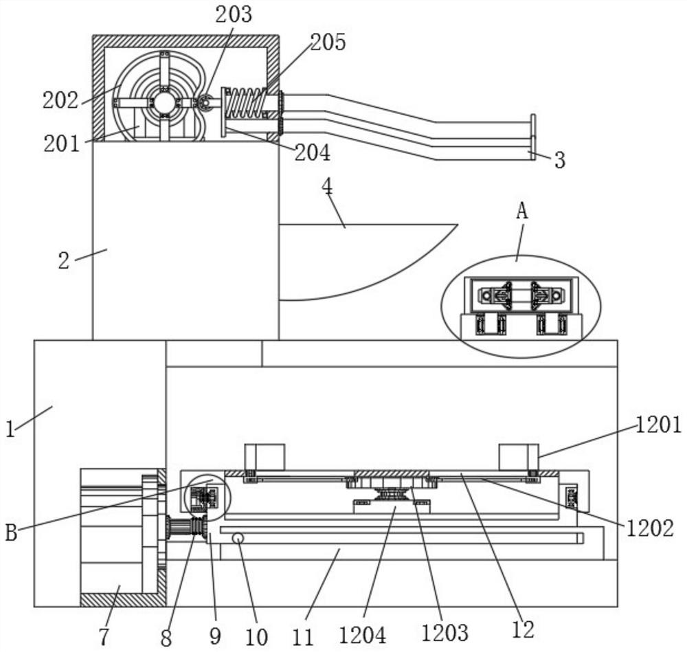
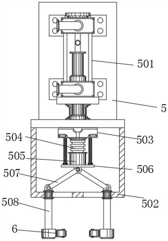
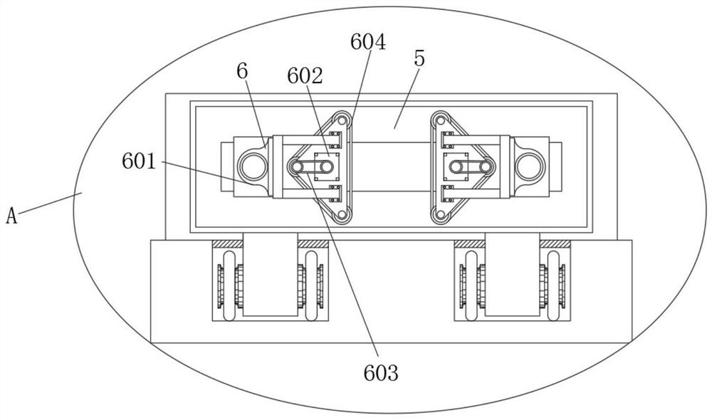
[0029] see Figure 1-6 , the present invention provides a technical solution: copper tube automatic positioning assembly processing equipment for the production of air-conditioning condensers, including a bottom chassis 1, a copper tube transmission component 2 is fixedly installed on the left side of the top end surface of the bottom chassis 1, and a copper tube transmission component 2 The first servo motor 201 is fixedly installed with bolts on the top layer of t...


PUM


Abstract

The invention discloses automatic positioning, assembling and machining equipment for copper pipes for production of air conditioner condensers. The automatic positioning, assembling and machining equipment comprises a bottom case, and a copper pipe conveying assembly is fixedly installed on the left side of the top end face of the bottom case through bolts. According to the automatic positioning, assembling and machining equipment, the copper pipe conveying assembly and a fin clamping assembly are arranged at the top and the interior of the bottom case correspondingly, and the copper pipe conveying assembly and a copper pipe flow guide frame are arranged, so that the effects of collecting and interval conveying of the copper pipes are facilitated; meanwhile, the fin clamping assembly and a sliding base are arranged, so that a fin main body is conveniently clamped and fixed, and meanwhile, the effect of controlling previous horizontal movement is achieved; the copper pipe clamping assembly and the copper pipe conveying assembly are arranged, so that the copper pipes are conveniently clamped and fixed; and meanwhile, the copper pipes are driven to move up and down, the copper pipes are conveniently driven to be separated from the copper pipe flow guide frame, ,the copper pipes and the fin main body are installed, so that the time and labor consumption and the productivity reduction during manual installation are avoided, the personnel cost can be reduced, and the productivity can be accelerated.

Description

technical field [0001] The invention relates to the technical field of air-conditioning production equipment, in particular to automatic positioning and assembling processing equipment for copper tubes used in the production of air-conditioning condensers. Background technique [0002] When the household air conditioner is cooling, the heat exchanger in the outdoor unit is called the condenser, and the heat exchanger in the indoor unit is called the evaporator. The heat release process of the condenser is to combine the high-temperature and high-pressure gaseous Freon with the air outdoors. Carry out heat exchange and turn into low-temperature and high-pressure liquid Freon. The condenser, that is, the outdoor heat exchanger, is the high-pressure equipment of the system during refrigeration. The high-pressure gas enters the condenser, and is cooled by copper tubes and aluminum foils. The air conditioners are equipped with axial flow cooling fans, which are air-cooled, so tha...

Claims


Application Information

Patent Timeline
IPC IPC(8): B23P19/00
CPCB23P19/00B23P19/001
Inventor 胡小影江文娟
Owner 温州纽木信息科技有限公司
Learn More