Device for fastening grinding wheel of vertical surface grinding machine with rotary table

A technology for surface grinders and fastening devices, which is applied to devices for fixing grinding wheels, grinding machines, and machine tools suitable for grinding workpiece planes, etc. It can solve the problems of reducing production efficiency, trouble, time-consuming and laborious, and achieve the effect of preventing loosening

Active Publication Date: 2021-05-28
烟台鑫硕机械有限公司
View PDF19 Cites 0 Cited by
  • Summary
  • Abstract
  • Description
  • Claims
  • Application Information

AI Technical Summary

Problems solved by technology

[0005] 1. Since the grinding wheel needs to be in contact with the workpiece during grinding, the grinding wheel may become loose when the contact force is strong or it is processed for a long time, so that the workpiece cannot be accurately ground and cut, which does not meet the production standards and requires It is very troublesome to adjust;
[0006] 2. When the grinding wheel is loose, its friction will also increase, which will reduce the life of the grinding wheel, resulting in frequent replacement of the grinding wheel, and the replacement of the grinding wheel is very troublesome, and the replaced grinding wheel may not match the grinding machine, which is time-consuming Laborious while reducing production efficiency

Method used


Image

  • Device for fastening grinding wheel of vertical surface grinding machine with rotary table
  • Device for fastening grinding wheel of vertical surface grinding machine with rotary table
  • Device for fastening grinding wheel of vertical surface grinding machine with rotary table

Examples


Embodiment Construction

[0023] The technical solutions in the embodiments of the present invention will be clearly and completely described below in conjunction with the accompanying drawings in the embodiments of the present invention. Obviously, the described embodiments are only some of the embodiments of the present invention, not all of them. Based on The embodiments in the invention, and all other embodiments obtained by persons of ordinary skill in the art without creative efforts, all belong to the scope of protection of the present invention.

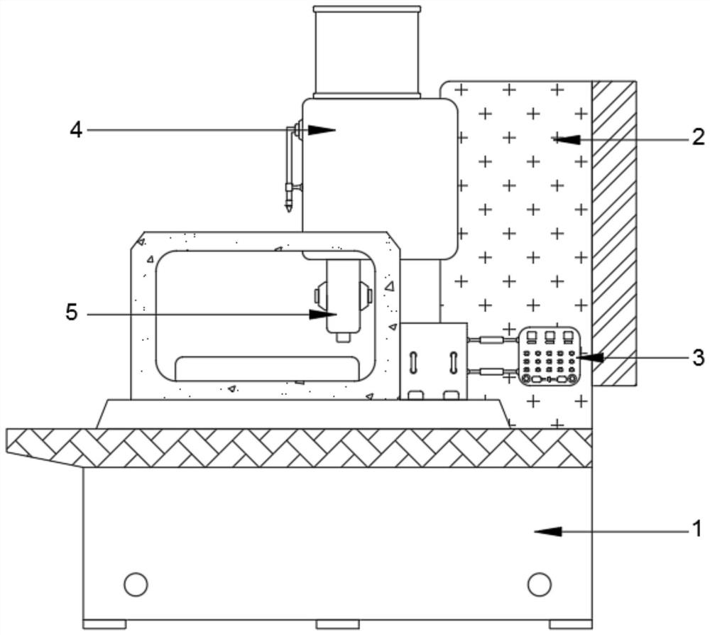
[0024] see figure 1 , a vertical round table surface grinder grinding wheel fastening device, including a bottom box 1, the top right side of the bottom box 1 is fixedly installed with a fuselage 2, the left top of the fuselage 2 is movably connected with a processing table 4, and the processing table 4 A grinding assembly 5 is fixedly installed at the bottom, and a control panel 3 is movably connected to the bottom of the front of the fuselage 2;

...


PUM


Abstract

The invention relates to the technical field of part grinding machining devices, and discloses a device for fastening a grinding wheel of a vertical surface grinding machine with a rotary table. The device comprises a bottom box, a machine body is fixedly arranged on the right side of the top end of the bottom box, a machining table is movably connected to the top of the left side of the machine body, and a grinding assembly is fixedly arranged at the bottom end of the machining table. According to the device for fastening the grinding wheel of the vertical surface grinding machine with a rotary table, in the rotating process of a rotating shaft, lead blocks drive telescopic rods to stretch out through the rotating shaft, then anti-collision pads on the surfaces of the lead blocks make contact with a rotating plate during rotation, moving rods extrude springback rods and move under the rotating force of the rotating plate, the moving rods drive a rotating disc to rotate when moving, the rotating disc rotates to enable transmission belts and accessory structures thereof to move, sliding blocks are driven by connecting rods to slide on the inner walls of hollow pipes, the moving sliding blocks enable inclined rods to drive touch rods to move, the touch rods move towards supporting columns through sliding sleeves at the top and the bottom, the touch rods move to make contact with fixed pads and drive the fixed pads to be fixed with the supporting columns, and then the grinding wheel is prevented from loosening.

Description

technical field [0001] The invention relates to the technical field of parts grinding and processing equipment, in particular to a grinding wheel fastening device for a vertical round table surface grinder. [0002] technical background [0003] The vertical round table grinder is a vertical grinding head and a circular electromagnetic workbench. It uses the cross section of the grinding wheel to grind the surface of the workpiece. The processing efficiency is high. The round table surface grinder is suitable for generators, tools, bearings, magnetic materials, refractory materials, molds, It is an indispensable equipment in modern industrial production when surface grinding is required in mold blanks, machinery and other industries. [0004] The general grinding machine often has the following two defects in the processing process: [0005] 1. Since the grinding wheel needs to be in contact with the workpiece during grinding, the grinding wheel may become loose when the con...

Claims


Application Information

Patent Timeline
IPC IPC(8): B24B7/00B24B41/047B24B45/00
CPCB24B7/00B24B41/047B24B45/003
Inventor 张俊芳
Owner 烟台鑫硕机械有限公司
Why Eureka
Try Eureka