
Air floatation vertical movement device

A technology of vertical motion and air flotation, applied in the direction of tool storage devices, electrical components, electrical components, etc., can solve the problems of complex structure, cumbersome process, huge overall structure, etc., and achieve reduced structure, reduced size, and compact structure. Effect

Pending Publication Date: 2021-05-28
YINGUAN SEMICON TECH CO LTD
View PDF0 Cites 0 Cited by
  • Summary
  • Abstract
  • Description
  • Claims
  • Application Information

AI Technical Summary

Problems solved by technology

The existing vertical motion device has a complex structure and a large overall structure. The relative movement of the lead screw and the guide rail matched with the lead screw will cause friction, which reduces the accuracy of the vertical motion device, and the lead screw and guide rail often need to be cleaned and replaced regularly. , the process is cumbersome

Method used


Image

  • Air floatation vertical movement device
  • Air floatation vertical movement device
  • Air floatation vertical movement device

Examples


Embodiment 1

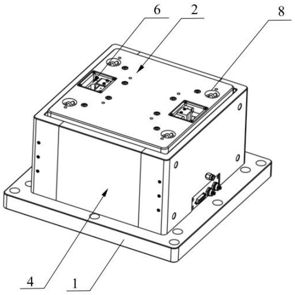
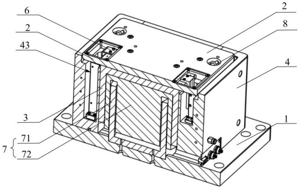
[0038]This embodiment provides a gas floating vertical moving device, which relates to the field of integrated circuitry manufacturing, such asFigure 1 to 4 As shown, the air floating vertical migration device includes a tray 2, a motor 7, a gas floating shaft 3, and a gas floating sleeve 4 in which the air floating shaft 3 is connected, the air floating shaft 3 is connected to the tray 2, the air floex 3 and the air float The sleeve 4 forms an air floating rail, and the motor 7 is provided in the air floating shaft 3, and the output of the motor 7 is connected to the air floating shaft 3, and the motor 7 drives the air floating shaft 3 to move the tray 2 in the axial direction of the gas floating rail.

[0039]The tray 2 of the present embodiment is used to present the processing workpiece, and the air floating shaft 3 is connected to the tray 2, allowing the air floating shaft 3 to move the tray 2 vertically. A stable gas film is formed between the outer wall of the air floating shaf...

Embodiment 2

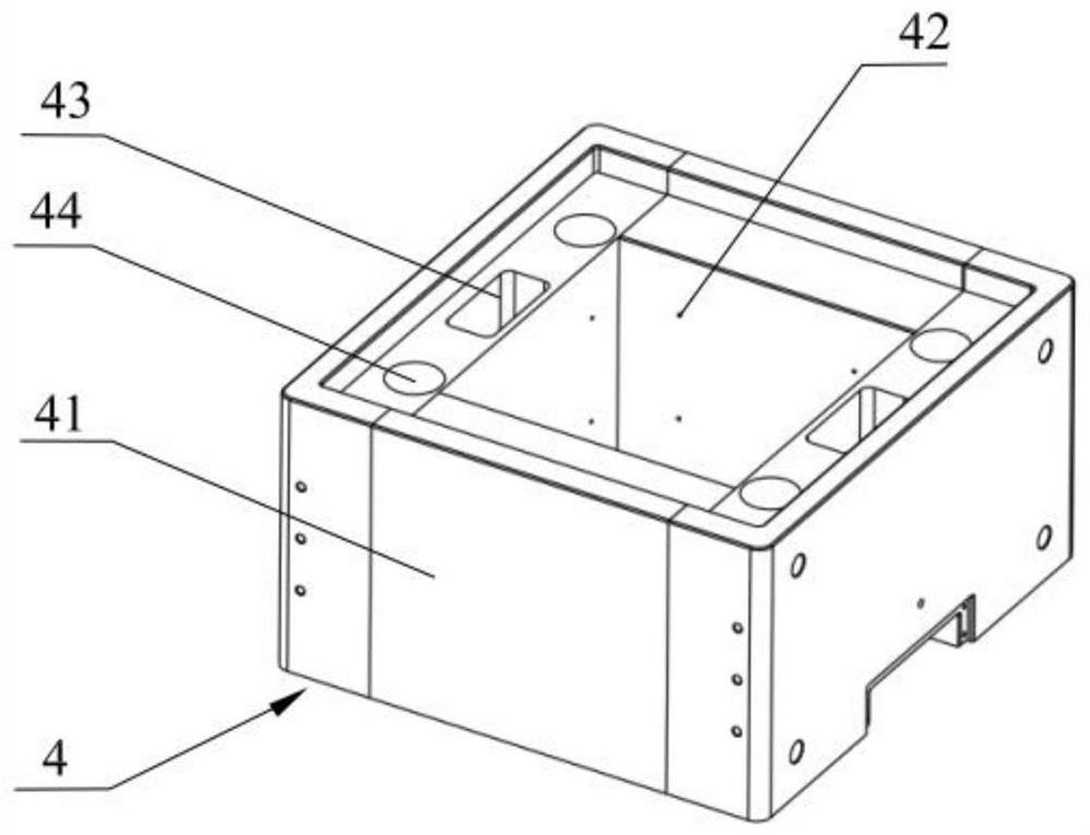
[0056]In this first embodiment, an air floating traveling device is disclosed. The first example gas floating shaft 3, the motor 7, the tray 2, and the base 1 are identical to the embodiment, and the difference between the embodiments and the embodiment is only in the implementation. The air floating sleeve 4 is integrally formed. Such asFigure 5 As shown, the air floating sleeve 4 is arranged in an integrated structure, and the processing difficulty of the air flub 4 is reduced, and the processing step is reduced. In this embodiment, a pipeline assembly 5, a pipeline assembly 5 communicates with a gas supply assembly is provided in the air floating sleeve 4, and the gas assembly is transported from the air supply assembly to the guide rail space. The pipe assembly 5 can be provided in the outer wall of the air floating 4 or within the air flop 4.

Embodiment 3

[0058]The third embodiment discloses an air floating vertical moving device, the present embodiment, the tray 2, and the base 1 are the same as the embodiment, and the difference between the present embodiment and the embodiment is only the air flurch of the present embodiment. 4 includes three panels 41, such asFigure 6 As shown, the three panels 41 are connected to each other, and the air floating shaft 3 of the present embodiment is also three prisms. That is, the air floating sleeve 4 includes three inner walls, and the air floating shaft 3 includes three outer walls, and the pipe assembly 5 can be disposed in the outer wall of the air floating sleeve 4, and may be embedded within the air floating sleeve 4, as long as the transport gas function is achieved.


PUM


Abstract

The invention provides an air floatation vertical movement device which comprises a tray, a motor, an air floatation shaft and an air floatation sleeve arranged on the air floatation shaft in a sleeving manner. The air floatation shaft is connected to the tray, the air floatation shaft and the air floatation sleeve form an air floatation guide rail, the motor is arranged in the air floatation shaft, and the output end of the motor is connected to the air floatation shaft. The motor drives the air floating shaft to drive the tray to move in the axis direction of the air floating guide rail. The outer wall of the air floatation shaft is in clearance fit with the inner wall of the air floatation sleeve to form a layer of stable air film, so that the air floatation guide rail is formed, and the air floatation guide rail plays a role in guiding the vertical movement of the air floatation shaft. The motor is arranged in the air floatation shaft, the structure is compact, the structure of the whole device is reduced, and the size of the occupied space of the device is reduced; and then the output end of the motor is connected to the air floatation shaft, and the air floatation shaft is driven by the motor to enable the air floatation shaft and the tray to move in the axis direction of the air floatation guide rail.

Description

Technical field[0001]The present invention relates to the field of integrated circuitry manufacturing, and more particularly to an air floating and vertical moving device.Background technique[0002]In recent years, as the integrated integrated circuit device integration is continuously improved, the accuracy and yield requirements of the integrated circuit processing workpiece are continuously improved, and the operation speed, acceleration and performance requirements of the vertical motion device are constantly increasing. The vertical motion device is mainly used in the semiconductor industry, the photoelectric industry, the integrated circuit, and the quality test of the components. Therefore, for the compact structure, the demand for the vertical motion device with higher performance is very urgent. The existing vertical motion device is rotated as a driving force, the screw as the transmission portion, the guide rail as a motion, and the motor is vertically moved along the guid...

Claims


Application Information

Patent Timeline
IPC IPC(8): B25H3/06H05K13/02
CPCB25H3/06H05K13/02
Inventor 陈啸虎江旭初吴火亮袁嘉欣唐艳文董亚聪
Owner YINGUAN SEMICON TECH CO LTD
Learn More