Automatic packaging device for circuit breaker production
An automatic packaging and circuit breaker technology, applied in packaging and other directions, can solve problems affecting work progress, large labor force, consumption, etc., and achieve the effect of preventing displacement
- Summary
- Abstract
- Description
- Claims
- Application Information
AI Technical Summary
Problems solved by technology
Method used
Image
Examples
Embodiment 1
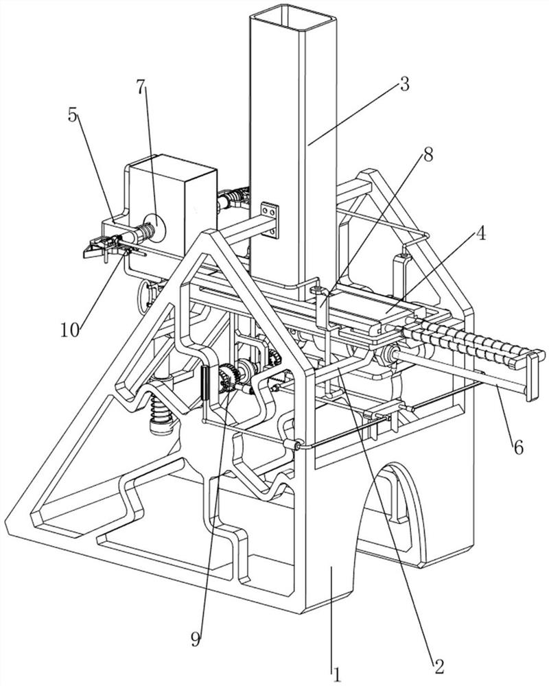
[0075]Automatic packaging device for circuit breaker production, such asfigure 1 As shown, including the leg 1, the rail plate 2, the discharge frame 3, the push mechanism 4, and the moving mechanism 5, and there is a rail plate 2 between the legs 1 on the front and rear sides, between the legs 1 between the front and rear sides. A discharge frame 3 is provided, and a push mechanism 4 is provided on the right side of the rail plate 2, and a moving mechanism 5 is provided on the left side of the rail plate 2.
[0076]When people need to pack the circuit breaker, this circuit breaker can be used to produce automatic packaging devices. First, people need to pour a number of circuit breakers into the discharge frame 3, then place the package on the mobile mechanism 5, Then push the push mechanism 4 to the left movement, push the circuit breaker to the package on the mobile mechanism 5, and then push the moving mechanism 5 in the compressed state 5 downward, and when the push mechanism 4 is...
Embodiment 2
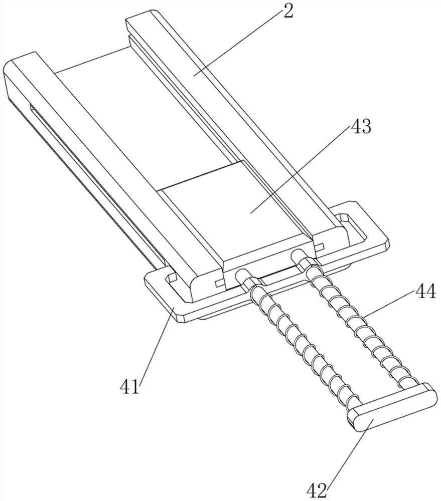
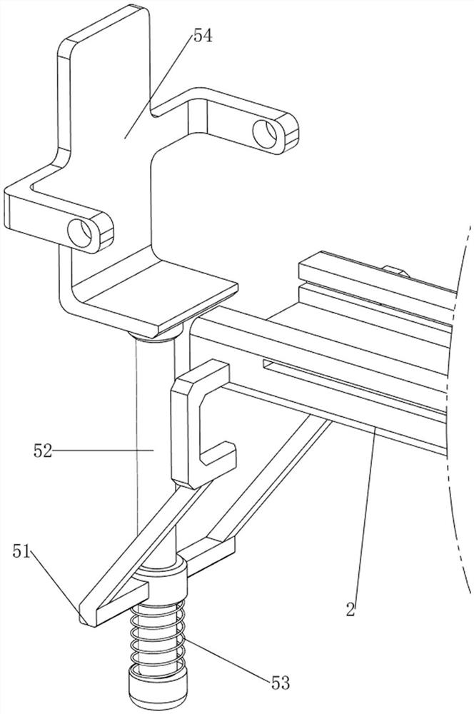
[0078]On the basis of Example 1, such asfigure 2 withimage 3 As shown, the pusher 4 includes a first slider 41, a first slider 42, a slider 43, and a first spring 44, and the first slider 41 is provided on the right side of the rail plate 2, and the first slider 41 right. The side intermediate sliding type is provided with a first slider 42, and the inner wall sliding type in the right side of the rail plate 2 is provided with a slider 43. The left side of the slider 43 is slidable on the left side of the first slider 42, and the first slider 42 before and after On both sides, there is a first spring 44, and the first spring 44 is connected to the first slider 42, respectively.
[0079]When a few circuit breakers are inserted into the discharge frame 3, then manually push the first slider 42 to slide left, the first spring 44 is compressed, so that the slider 43 is moved to the left, so that the slider 43 can The circuit breaker is introduced, and the effect of the push is achieved. At...
Embodiment 3
[0083]On the basis of Example 2, such asFigure 4 - Figure 8As shown, there is a drive mechanism 6, the drive mechanism 6 includes a first mounting block 61, a cylinder 62, a piston rod 63, and a push block 64, and a first mounting block 61 is provided at the bottom right side of the rail plate 2, the first mounting A cylinder 62 is mounted on the block 61, and a piston rod 63 is provided on the telescopic rod of the cylinder 62, and a piston rod 64 is provided on the right side of the piston rod 64, and the push block 64 cooperates with the first slider 42.
[0084]When the cylinder 62 is activated, the telescopic rod of the cylinder 62 drives the piston rod 63 to the left motion to move to the left, so that the piston rod 63 is in contact with the first slider 42, so that the first slider 42 is moved to the left, which can automatically pose, realize The effect of the drive, and when the telescopic rod of the cylinder 62 drives the piston rod 63 to the right, the piston rod 63 is not ...
PUM
 Abstract
Description
Claims
Application Information
 - R&D
- Intellectual Property
- Life Sciences
- Materials
- Tech Scout
- Unparalleled Data Quality
- Higher Quality Content
- 60% Fewer Hallucinations
Browse by: Latest US Patents, China's latest patents, Technical Efficacy Thesaurus, Application Domain, Technology Topic, Popular Technical Reports.
© 2025 PatSnap. All rights reserved.Legal|Privacy policy|Modern Slavery Act Transparency Statement|Sitemap|About US| Contact US: help@patsnap.com


