Device and method for active control of lift in main cable-saddle slip state of suspension bridge

A technology of suspension bridges and saddles, applied in the direction of suspension bridges, bridges, bridge construction, etc., can solve the problems affecting the safety, stability and durability of the main tower, the unbalanced force of the main cable, the unbalanced force of the main tower, etc., to achieve Eliminate bolt connection or ferrule loading and unloading, increase friction, reduce friction

Active Publication Date: 2021-11-16
SOUTHEAST UNIV
View PDF0 Cites 0 Cited by
  • Summary
  • Abstract
  • Description
  • Claims
  • Application Information

AI Technical Summary

Problems solved by technology

[0002] During the construction of the stiffening girder of the suspension bridge, due to the imbalance of the main cable force on both sides of the main tower (that is, the imbalance of the main cable force along the longitudinal direction of the main cable), the root of the main tower bears a large bending moment, which seriously affects the safety of the main tower , stability and durability
In the actual construction process, the pre-deflection of the cable saddle is often used to reduce the impact of the unbalanced main cable force. However, the construction of this method is complicated, and the cable saddle needs to be pushed multiple times, and more refined calculation of the pre-deflection is required; Once there is an error in the calculation, it is almost impossible to correct the deviation, resulting in an unbalanced force on the main tower

Method used


Image

  • Device and method for active control of lift in main cable-saddle slip state of suspension bridge
  • Device and method for active control of lift in main cable-saddle slip state of suspension bridge
  • Device and method for active control of lift in main cable-saddle slip state of suspension bridge

Examples


Embodiment Construction

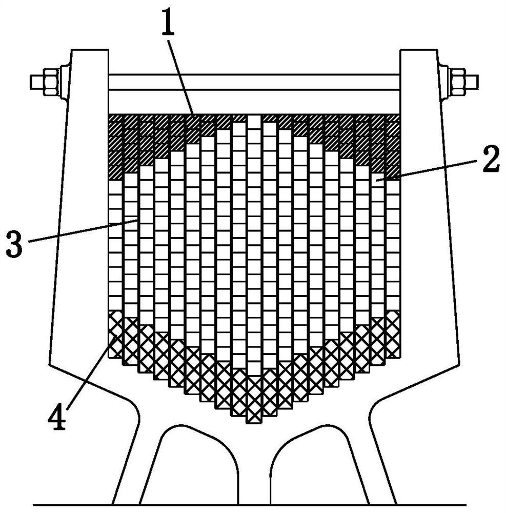
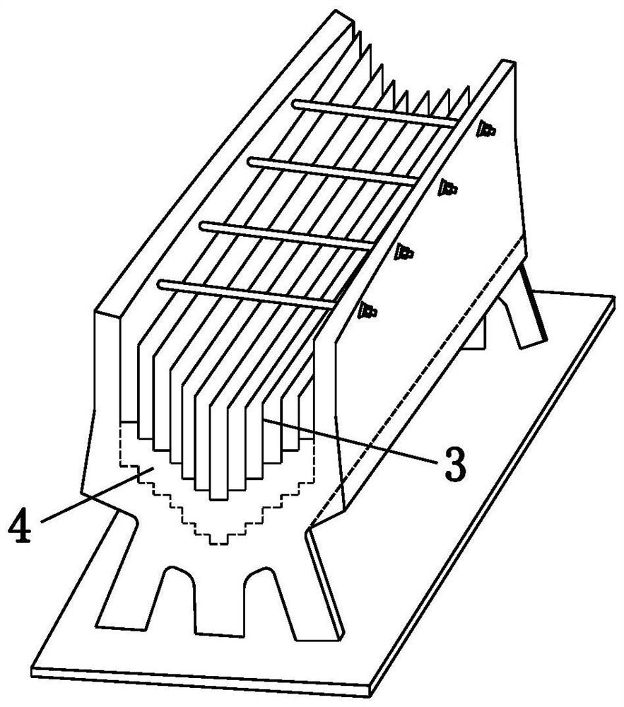
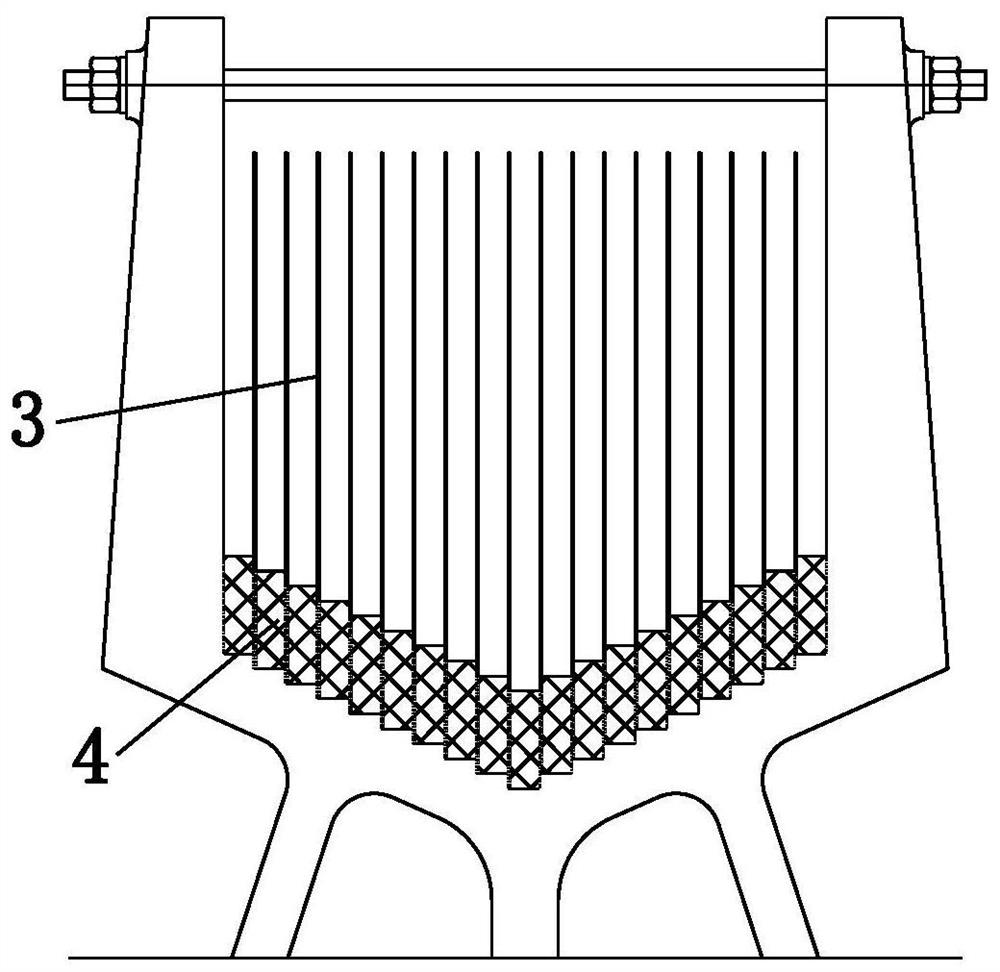
[0041] The present invention will be further described in detail below in conjunction with the accompanying drawings and specific preferred embodiments.

[0042]In the description of the present invention, it should be understood that the orientations or positional relationships indicated by the terms "left side", "right side", "upper", "lower" are based on the orientations or positional relationships shown in the accompanying drawings, and are only For the purpose of describing the present invention and simplifying the description, rather than indicating or implying that the device or element referred to must have a specific orientation, be constructed and operate in a specific orientation, "first", "second" and the like do not represent components importance, and therefore should not be construed as limiting the invention. The specific dimensions used in this embodiment are only for illustrating the technical solution, and do not limit the protection scope of the present inv...


PUM


Abstract

The invention discloses a suspension bridge main cable-saddle saddle slip state active control lift device and method, comprising a suspension electromagnet, a partition and a permanent magnet; the suspension electromagnet is embedded in the bottom of the saddle groove of the saddle; two adjacent pieces A cable strand groove is formed between the partitions; the number of each cable strand groove is equal to the number of cable strands; the suspension electromagnet located in each cable strand groove is equipped with several convex tooth electromagnets along the longitudinal bridge direction; each The top surfaces of each convex-tooth electromagnet are arc-shaped, and the top connecting lines of all convex-tooth electromagnets are arc-shaped arcs, and the shape of the arch-shaped arc is the same as that of the main cable after seating; among them, the convex-tooth electromagnets The cross-sectional area gradually decreases from the top of the arch to the bottom of the arch on both sides; a permanent magnet block with a cross-sectional area matching it is arranged above each convex tooth electromagnet; the top of each permanent magnet block There are pressure sensors on both sides. The invention can effectively eliminate the unbalanced force of the main cables on both sides of the main tower during the construction process of the suspension bridge.

Description

technical field [0001] The invention relates to the field of bridge engineering design and construction, in particular to a suspension bridge main cable-saddle slip state active control lift device and method. Background technique [0002] During the construction of the stiffening girder of the suspension bridge, due to the imbalance of the main cable force on both sides of the main tower (that is, the imbalance of the main cable force along the longitudinal direction of the main cable), the root of the main tower bears a large bending moment, which seriously affects the safety of the main tower , stability and durability. In the actual construction process, the pre-deflection of the cable saddle is often used to reduce the impact of the unbalanced main cable force. However, the construction of this method is complicated, and the cable saddle needs to be pushed multiple times, and more refined calculation of the pre-deflection is required; Once there is an error in the calc...

Claims


Application Information

Patent Timeline
Patent Type & Authority Patents(China)
IPC IPC(8): E01D11/02E01D19/16E01D19/14E01D21/00
CPCE01D11/02E01D19/14E01D19/16E01D21/00
Inventor 熊文汪涛
Owner SOUTHEAST UNIV
Why Eureka
Try Eureka