Positioning fixture for metal machining

A technology for positioning molds and metal processing, applied in metal processing equipment, manufacturing tools, workpiece clamping devices, etc. The effect of reducing longitudinal pressure

Inactive Publication Date: 2020-02-04
韶关市淇远机械科技有限公司
View PDF0 Cites 0 Cited by
  • Summary
  • Abstract
  • Description
  • Claims
  • Application Information

AI Technical Summary

Problems solved by technology

[0002] In many metal processing occasions, there are coaxiality requirements for mechanical components with holes, whether they are assembled or welded. Generally, if there is a coaxiality requirement for assembly parts, a through shaft will be installed in series with the mechanical components. In the process of positioning to solve the coaxiality problem in the process of coaxial assembly and welding, in actual operation, the through shaft and the hole are matched by subtraction, so there will be a gap, because there will be a gap in the mechanical components during the assembly and welding process Displacement in different directions, clamping the through shaft makes disassembly difficult. During disassembly, it is necessary to hit hard or press hard to push the through shaft out, so that the coaxial accuracy cannot be guaranteed during the operation. Therefore, it is necessary to design a belt Coaxial positioning device for hole metal

Method used


Image

  • Positioning fixture for metal machining
  • Positioning fixture for metal machining
  • Positioning fixture for metal machining

Examples


Embodiment Construction

[0016] The following will clearly and completely describe the technical solutions in the embodiments of the present invention with reference to the accompanying drawings in the embodiments of the present invention. Obviously, the described embodiments are only some, not all, embodiments of the present invention.

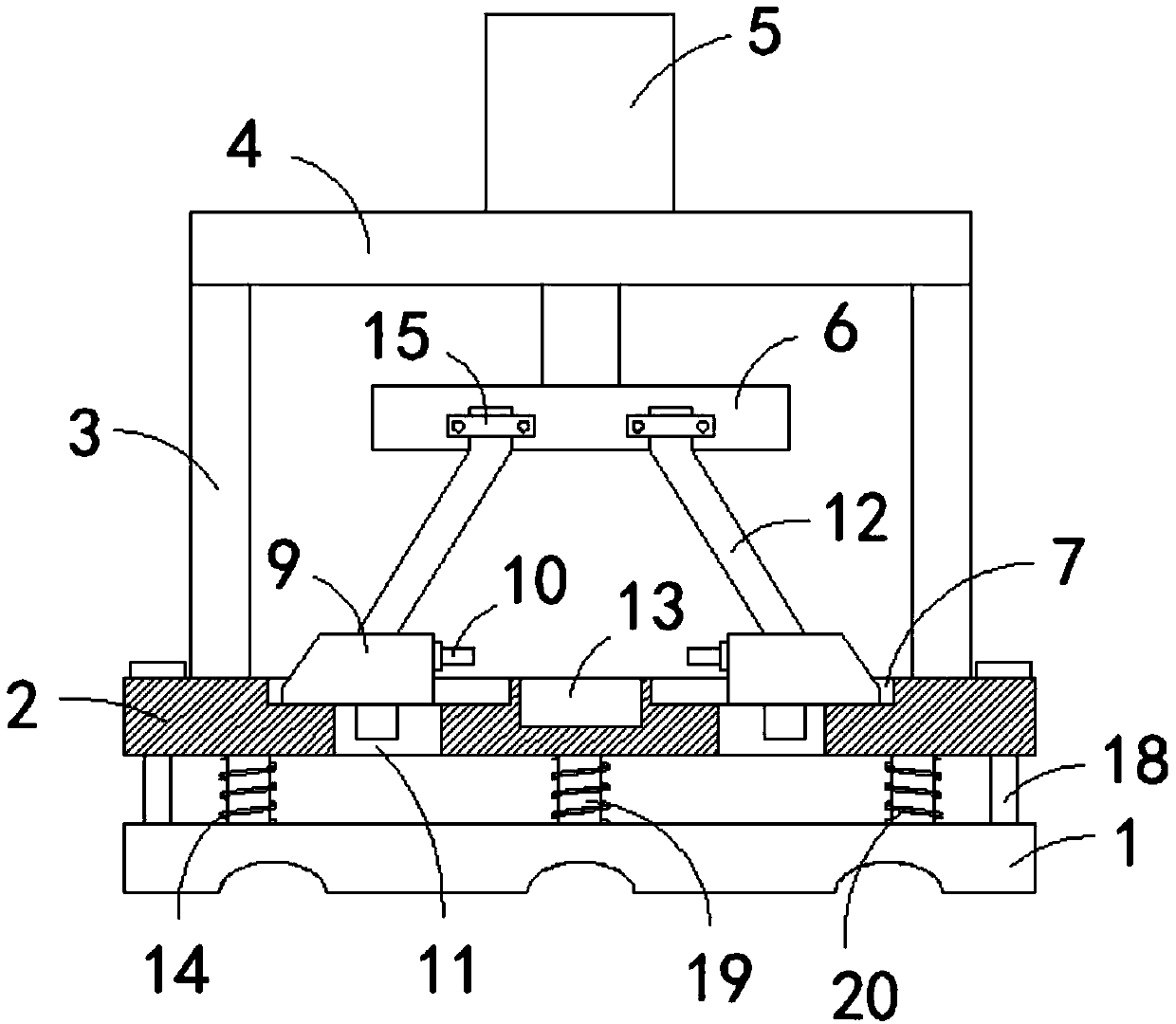
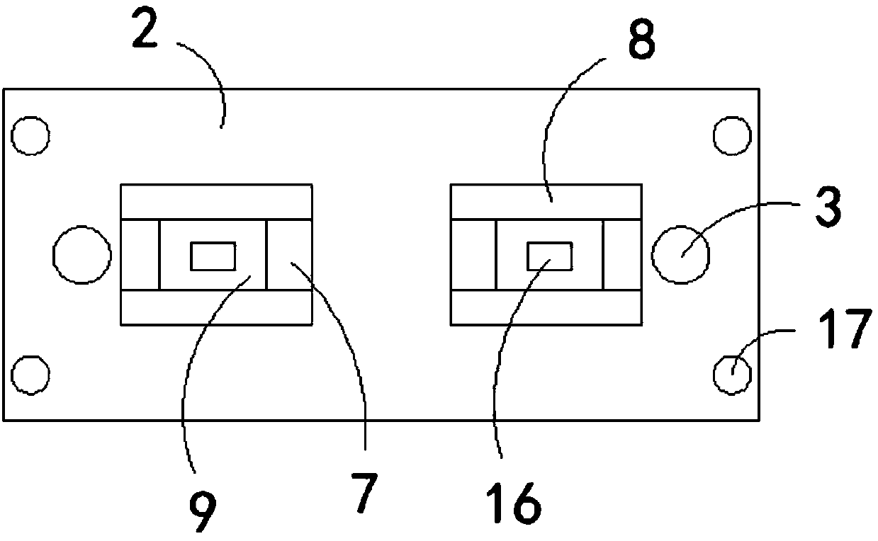
[0017] refer to Figure 1-3 , a positioning mold for metal processing, comprising a support base 1 and a workbench 2, two vertical support rods 3 are fixedly connected to the top wall of the workbench 2, and two vertical support rods 3 are fixedly connected to the top wall of the two support rods 3 Horizontal plate 4, a hydraulic cylinder 5 is installed in the center of the top wall of the horizontal plate 4, the piston end of the hydraulic cylinder 5 runs through the horizontal plate 4 and is fixedly connected with a horizontal mounting block 6, and the top wall of the workbench 2 is provided with two rectangular recesses. The groove 7, the front and rear inner wall...


PUM


Abstract

The invention discloses a positioning fixture for metal machining. The positioning fixture comprises a supporting base and a workbench, wherein two vertical supporting rods are fixedly connected to the top wall of the workbench, a transverse plate is fixedly connected to the top walls of the two supporting rods, a hydraulic cylinder is installed in the center of the top wall of the transverse plate, and the piston end of the hydraulic cylinder penetrates through the transverse plate to be fixedly connected with a horizontal mounting block; and two rectangular grooves are formed in the top wallof the workbench, limiting blocks are fixedly connected to the front and rear inner walls of each rectangular groove, trapezoidal blocks are slidably connected between the two corresponding limitingblocks, limiting rods are fixedly connected to the opposite end faces of the two corresponding trapezoidal blocks, openings communicating with the rectangular grooves are formed in the bottom wall ofthe workbench, and two mounting grooves are formed in the bottom wall of the mounting block. According to the positioning fixture, coaxial positioning treatment on perforated metal is facilitated, thecoaxial precision of the metal during machining is ensured, and the machining stability is improved.

Description

technical field [0001] The invention relates to the technical field of metal processing, in particular to a positioning mold for metal processing. Background technique [0002] In many metal processing occasions, there are coaxiality requirements for mechanical components with holes, whether they are assembled or welded. Generally, if there is a coaxiality requirement for assembly parts, a through shaft will be installed in series with the mechanical components. In the process of positioning to solve the coaxiality problem in the process of coaxial assembly and welding, in actual operation, the through shaft and the hole are matched by subtraction, so there will be a gap, because there will be a gap in the mechanical components during the assembly and welding process Displacement in different directions, clamping the through shaft makes disassembly difficult. During disassembly, it is necessary to hit hard or press hard to push the through shaft out, so that the coaxial accu...

Claims


Application Information

Patent Timeline
IPC IPC(8): B25B11/00B25B11/02B23K37/04
CPCB23K37/04B23K37/0443B25B11/00B25B11/02
Inventor 谢凤清
Owner 韶关市淇远机械科技有限公司
Why Eureka
Try Eureka