
Air exhaust type drainage device for water-rich foundation pit with low permeability coefficient and construction method

A drainage device and air pumping technology, which is applied in infrastructure engineering, construction, etc., can solve the problems of cumbersome construction techniques for electroosmotic well point dewatering and jet well point dewatering, increased construction difficulty and high construction cost of water-stop curtains, and achieve The effect of saving construction labor cost, fast construction speed and low cost

Inactive Publication Date: 2021-05-28
SINOHYDRO BUREAU 5
View PDF6 Cites 2 Cited by
  • Summary
  • Abstract
  • Description
  • Claims
  • Application Information

AI Technical Summary

Problems solved by technology

[0010] The technical problem to be solved in the present invention is: for the soil layer with low permeability coefficient, the conventional tube well dewatering method cannot be used, the construction technology of electroosmotic well point dewatering and jet well point dewatering is cumbersome, and the construction cost is high. When it is deeper, the construction difficulty of the water-stop curtain increases greatly with the increase of depth

Method used


Image

  • Air exhaust type drainage device for water-rich foundation pit with low permeability coefficient and construction method
  • Air exhaust type drainage device for water-rich foundation pit with low permeability coefficient and construction method
  • Air exhaust type drainage device for water-rich foundation pit with low permeability coefficient and construction method

Examples


Embodiment Construction

[0028] The present invention will be described in further detail below in conjunction with the accompanying drawings and specific embodiments.

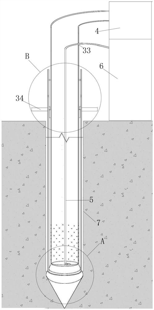
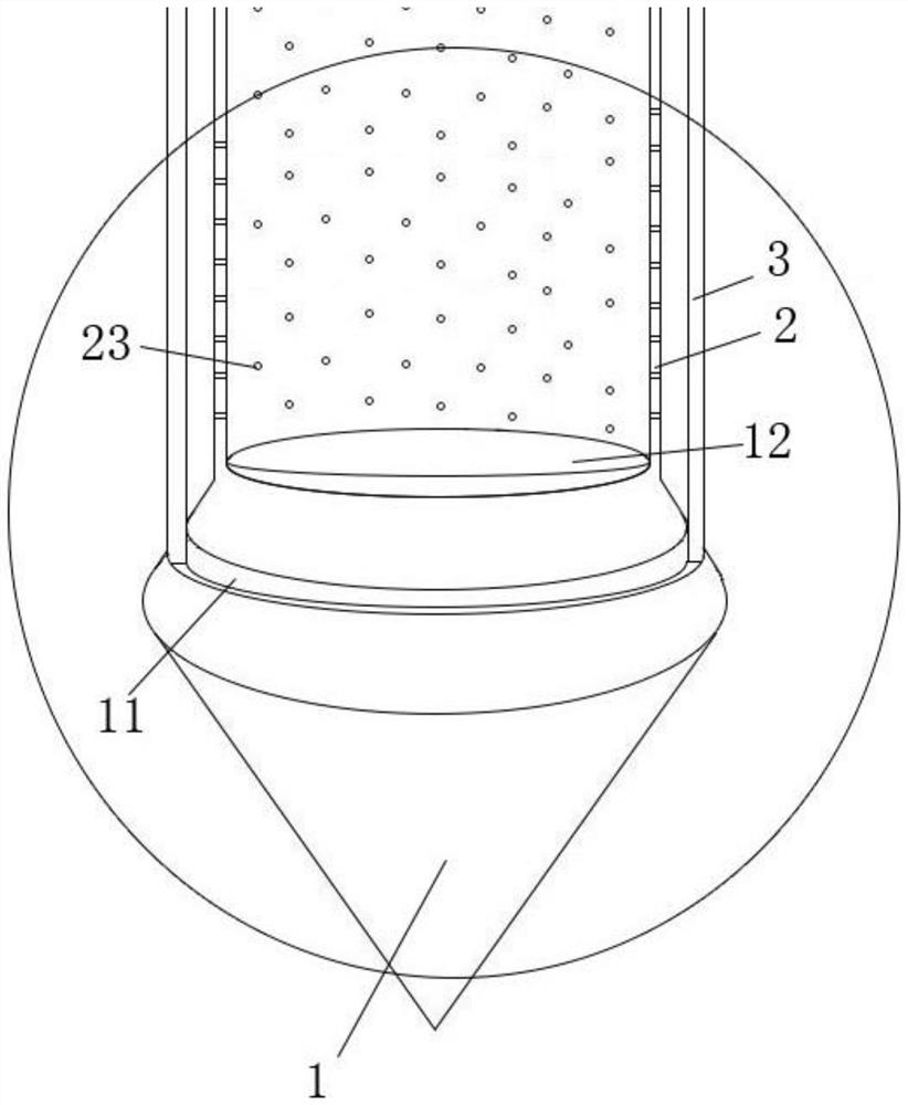
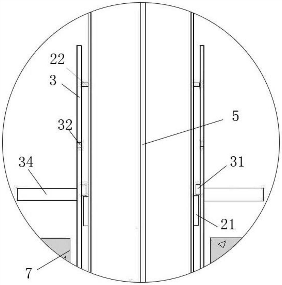
[0029] A pumping type drainage device for low permeability coefficient rich water foundation pit, comprising a drill bit 1, an inner tube 2 connected to the upper end of the drill bit 1 and an outer tube 3 sleeved outside the inner tube 2; the drill bit 1 is The tip of the tapered body facing downwards has a positioning groove 11 on the periphery of its top, and a rubber lining is provided in the positioning groove 11; it also includes some water seepage holes 23 arranged on the lower half of the inner tube 2, and the top of the inner tube 2 is connected to the inner tube. The small rotary vane vacuum pump 4 is connected; the length of the inner pipe 2 is longer than the length of the outer pipe 3, and a water suction hose 5 is arranged inside the inner pipe 2, and the lower end of the water suction hose 5 is placed on the upper end su...


PUM


Abstract

The invention discloses an air exhaust type drainage device for a low-permeability-coefficient water-rich foundation pit and a construction method. The air exhaust type drainage device comprises a drill bit and an outer pipe arranged outside an inner pipe in a sleeving mode; a positioning groove is formed in the periphery of the top end of the drill bit and internally provided with a rubber lining; the air exhaust type drainage device further comprises water seepage holes formed in the lower half pipe body of the inner pipe; and a water suction hose is arranged in the inner pipe, the lower end of the water suction hose is coiled in a downwards-sunken arc-shaped groove in the upper end face of the drill bit, and the upper end of the water suction hose penetrates through a hose hole in the side wall of the top of the inner pipe and then is connected with a small water pump. The construction speed is high, drainage is conducted from the peripheral side of the foundation pit through mounting holes, and the influence on the foundation pit is avoided; a negative pressure state is created in the inner pipe in an air suction type drainage mode, the device is suitable for drainage of a soil layer with a low permeability coefficient and is also suitable for foundation pit soil layers under other working conditions, and the universality is high; and meanwhile, the cost is low, a constructor does not need to watch at any time, the construction labor cost is saved, and high economic benefits are achieved.

Description

technical field [0001] The invention relates to the field of supporting devices for foundation pit construction, in particular to an air-pumping drainage device and a construction method for low-permeability-coefficient rich-water foundation pits. Background technique [0002] In recent years, with the continuous development of underground projects such as subways, tunnels, large-scale water conservancy projects, and high-rise building foundations, the construction of deep foundation pits has increasingly become an eye-catching technical difficulty and hot issue in construction engineering. How to control groundwater and reduce its negative impact on deep foundation pit excavation and concrete construction has become an important and difficult construction link in the construction of deep foundation pit underground buildings. [0003] When excavating deep foundation pits in areas with high groundwater levels, since the aquifer is cut off, under the action of pressure differe...

Claims


Application Information

Patent Timeline
Patent Type & Authority Applications(China)
IPC IPC(8): E02D19/06E02D19/10
CPCE02D19/06E02D19/10
Inventor 熊亮袁幸朝梁涛孙林智
Owner SINOHYDRO BUREAU 5
Learn More