Liquid-collecting flow-guiding assembly and device

A liquid collection and assembly technology, applied in exhaust gas devices, combustion product treatment, combustion methods, etc., can solve problems such as condensate pollution of the environment, achieve outstanding technical advantages, avoid secondary entrainment, and optimize the effect of the chimney flow field

Active Publication Date: 2021-05-28
SHANGHAI DEFOG ENVIRONMENTAL SCI & TECH
View PDF5 Cites 0 Cited by
  • Summary
  • Abstract
  • Description
  • Claims
  • Application Information

AI Technical Summary

Problems solved by technology

[0005] The technical purpose of the present invention is to provide a liquid collection and diversion assembly and device to solve the technical problem of environmental pollution caused by condensate in the wet desulfurization system

Method used


Image

  • Liquid-collecting flow-guiding assembly and device
  • Liquid-collecting flow-guiding assembly and device
  • Liquid-collecting flow-guiding assembly and device

Examples


Embodiment 1

[0043]In the vertical direction of the flue gas rising direction in the chimney 5, it is vertically in the horizontal direction of the flue gas rise.

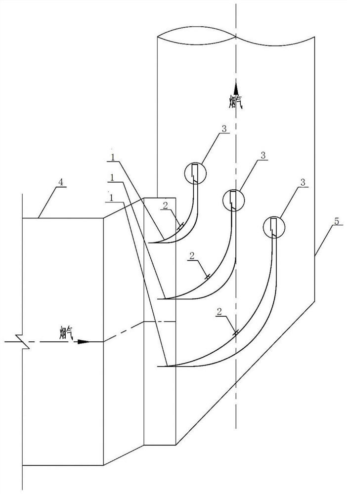
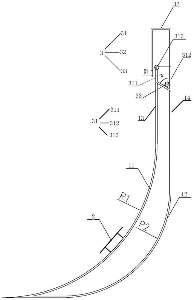
[0044]SeeFigure 1 to 5This embodiment provides a liquid collection flow assembly, including:

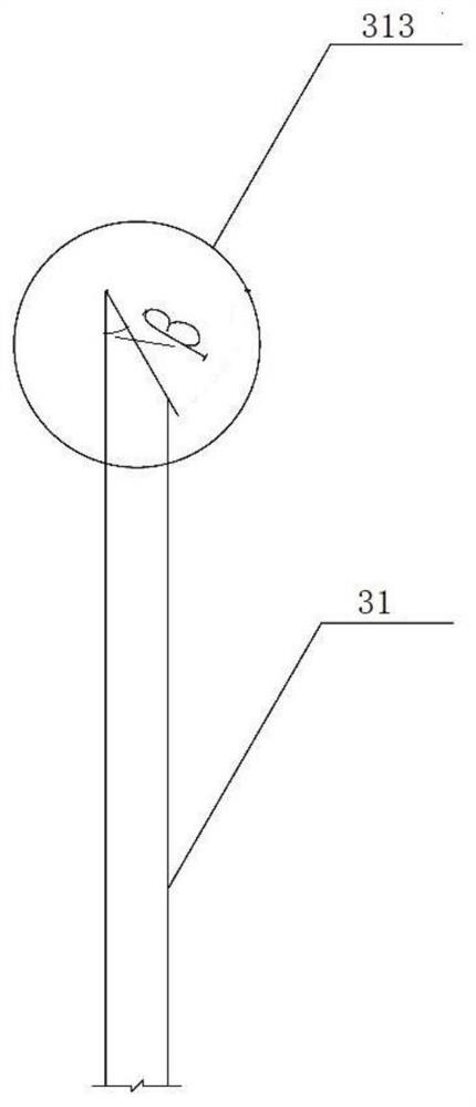
[0045]One or more heat exchange portions 1 disposed at the inlet of the lumen of the chimney 5, and the first collecting portion 2 and the second collecting portion 3 on the guide portion 1. On the left and right sides of the flow of the guide flow, the lumen wall surface is connected to the lumen surface of the chimney 5, and the flue gas flow channel is formed in the lumen surface of the chimney 5; wherein the flow channel 1 comprises the first and rear sides The circular arc surface and the second guiding surface, the center of the first passage of the arc surface and the second pilot curve is located on the same side of the guide portion 1, and the radius of the first passage arc surface is greater than the second guide. The radius of the arc...

Embodiment 2

[0055]Seefigure 1 In this embodiment, the present embodiment provides a liquid collection fluid device, from the entire working process to the liquid collection fluid flow from the whole process:

[0056]The cross-sectional size of the inner wall of the chimney 5, the cross-sectional size of the flue 4, the smoke port, and the simulation of the flue gas flow rate and combined with the CFD air flow tissue simulation, and several liquid collecting the flow of the flow of the flow of the flow rate increases step by step. The inner cavity of the chimney 5 or the adjacent flow passage portion 1 form a plurality of flue gas circulation channels, and the flue gas enters the chimney 5 after the flue 4, the flow of the flow line design of the flow of the liquid collecting the flow of the flow of the flow Next, the flue gas flow becomes slow, uniform, and the high flow rate is significantly reduced, and the flue gas flow field has been significantly improved, the system is compressed, and the op...


PUM


Abstract

The invention discloses a liquid-collecting flow-guiding assembly. The liquid-collecting flow-guiding assembly comprises at least one flow-guiding part which is used for being arranged in an inlet of an external chimney inner cavity, a first collecting part and a second collecting part, wherein the left and right sides of the flow-guiding part are used for being connected with inner cavity wall surfaces of the external chimney inlet respectively, and match the external chimney inner cavity or an adjacent flow-guiding part to form a smoke circulation channel; the flow-guiding part comprises a first flow-guiding cambered surface and a second flow-guiding cambered surface at the front and rear sides, circle centers of the first flow-guiding cambered surface and the second flow-guiding cambered surface are located at the same side, and the radius of the first flow-guiding cambered surface is larger than that of the second flow-guiding cambered surface; the first collecting part is arranged on the first flow-guiding cambered surface, and is used for collecting liquid, which flows upwards or downwards along the lower portion of the first flow-guiding cambered surface, in smoke; and the second collecting part is arranged at the top end of the flow-guiding part, and is used for intercepting and collecting the liquid in the smoke. After the smoke enters a chimney from a flue, change of a flow direction is made to be slower, a flow field of the smoke is made to be evener, and spaces for installation of the collecting parts are provided, so that a liquid-collecting function is achieved.

Description

Technical field[0001]The present invention belongs to the field of chimneys and flue design, and more particularly to a liquid collecting flow assembly and apparatus.Background technique[0002]More than 90% of the thermal electromechanical set of 300MW in my country use limestone - gypsum wet flue gas desulfurization technology. No GGH wet desulfurization system absorption tower export net flue gas temperature is about 50 ° C, in a saturated state of high moisture content. The flue gas discharges the absorption tower contains a certain entrained liquid, and in the process of flowing through the wet pipe and the wetting chimney, a large amount of condensate is precipitated by heat transfer condensation and adiabatic expansion, and if these liquids do not perform effective collection capture, It will be carried out of the chimney into a chimney rain. At present, there is currently no environment in which the wet smoke is mostly considering the environment of the wet smoke, nor has the ...

Claims


Application Information

Patent Timeline
Patent Type & Authority Applications(China)
IPC IPC(8): F23J13/00B01D45/08B01D53/00
CPCF23J13/00B01D45/08B01D53/002
Inventor 戴永阳吴永杰朱晓欣
Owner SHANGHAI DEFOG ENVIRONMENTAL SCI & TECH
Why Eureka
Try Eureka