Switch cabinet for textile machinery

A technology for textile machinery and switch cabinets, applied in the field of switch cabinets, can solve the problems of inconvenient cleaning of flying floes in switch cabinets, cross winding of lines, and easy moisture damage to circuit components.

Inactive Publication Date: 2021-05-28
江苏沁怡纺织品有限公司
View PDF0 Cites 2 Cited by
  • Summary
  • Abstract
  • Description
  • Claims
  • Application Information

AI Technical Summary

Problems solved by technology

[0007] The purpose of the present invention is to provide a switchgear for textile machinery to solve the problems in the above-mentioned background art that it is inconvenient to clean the flying catkins when the switchgear is in use, the lines are cross-wound, and the circuit components are easily damaged by moisture.

Method used


Image

  • Switch cabinet for textile machinery
  • Switch cabinet for textile machinery
  • Switch cabinet for textile machinery

Examples


Embodiment Construction

[0023] The following will clearly and completely describe the technical solutions in the embodiments of the present invention with reference to the accompanying drawings in the embodiments of the present invention. Obviously, the described embodiments are only some, not all, embodiments of the present invention. Based on the embodiments of the present invention, all other embodiments obtained by persons of ordinary skill in the art without making creative efforts belong to the protection scope of the present invention.

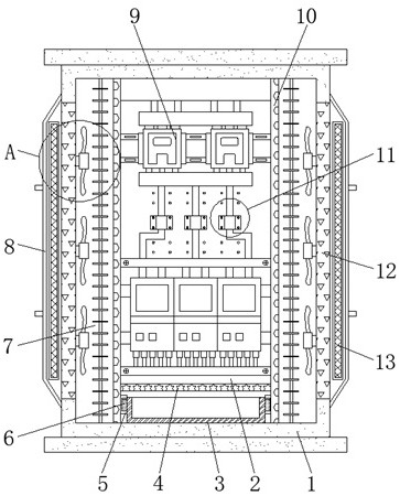
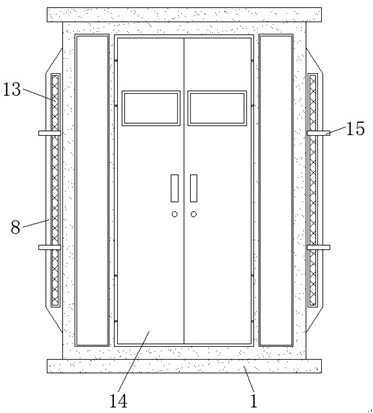
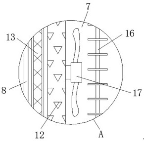
[0024] see Figure 1-4 , an embodiment provided by the present invention: a switch cabinet for textile machinery, including a cabinet body 1, a drying drawer 3, circuit components 9, hollow partitions 10 and a limit structure 11, the two sides inside the cabinet body 1 Hollow partitions 10 are fixed, and a power distribution chamber 2 is provided inside the cabinet body 1 between adjacent hollow partitions 10, and a cooling chamber is provided inside the cabin...


PUM


Abstract

A switch cabinet for textile machinery disclosed by the present invention comprises a cabinet body, a drying drawer, a circuit element, hollowed-out partition plates and a limiting structure, the hollowed-out partition plates are fixed on both sides of the interior of the cabinet body, a power distribution cavity is arranged in the cabinet body between the adjacent hollowed-out partition plates, a heat dissipation cavity is arranged in the cabinet body on one side of the hollowed-out partition plates away from the power distribution cavity, a hollow baffle is arranged at the bottom of the power distribution cavity, circuit elements are installed in the power distribution cavity above the hollow baffle, limiting structures are arranged on the inner walls of the cabinet body between the adjacent circuit elements, ventilation plates are fixed on the inner walls of the two sides of the cabinet body, and dust covers are fixed on the outer walls of the cabinet body at the positions of the ventilation plates. According to the invention, flying catkins are prevented from entering the cabinet body, the convenience of cleaning the flying catkins is improved, cross winding between lines is avoided, and the situation that circuit elements in the cabinet body are affected with damp and damaged is reduced.

Description

technical field [0001] The invention relates to the technical field of switch cabinets, in particular to a switch cabinet for textile machinery. Background technique [0002] The main function of the switchgear is to open and close, control and protect the electrical equipment in the process of power generation, transmission, distribution and power conversion in the power system. As a kind of electrical equipment, the switchgear plays an important role in many fields. , especially in the field of textile machinery, switch cabinets are used more frequently. [0003] There are many types of switch cabinets on the market today, which can basically meet people's needs, but there are still some shortcomings. The specific problems are as follows. [0004] (1) Existing switch cabinets of this type are usually equipped with heat dissipation holes for heat dissipation during use, and the factory buildings of textile machinery are usually filled with a large number of flying catkins,...

Claims


Application Information

Patent Timeline
Patent Type & Authority Applications(China)
IPC IPC(8): H02B1/30H02B1/28H02B1/56H02B1/20
CPCH02B1/20H02B1/28H02B1/30H02B1/565
Inventor 不公告发明人
Owner 江苏沁怡纺织品有限公司
Why Eureka
Try Eureka