
Multifunctional switch cabinet convenient to support and adjust

A multi-functional switch and cabinet technology, which is applied in substation/switch layout details, substation/switchgear cooling/ventilation, electrostatic cleaning, etc., can solve problems affecting the working efficiency of switch cabinets, time-consuming and labor-intensive, etc., to prevent The effect of cabinet movement, avoiding short circuit, and convenient movement

Active Publication Date: 2021-05-28
中科瑞能电气股份有限公司
View PDF12 Cites 0 Cited by
  • Summary
  • Abstract
  • Description
  • Claims
  • Application Information

AI Technical Summary

Problems solved by technology

[0004] The present invention provides a multifunctional switchgear that is easy to support and adjust, which can effectively solve the problem of the existing switchgear proposed in the above background technology. Due to the large volume of the switchgear , when moving and adjusting the switchgear, multiple people are required to carry out the adjustment, which is time-consuming and laborious, and affects the working efficiency of the switchgear

Method used


Image

  • Multifunctional switch cabinet convenient to support and adjust
  • Multifunctional switch cabinet convenient to support and adjust
  • Multifunctional switch cabinet convenient to support and adjust

Examples


Embodiment Construction

[0035] The preferred embodiments of the present invention will be described below in conjunction with the accompanying drawings. It should be understood that the preferred embodiments described here are only used to illustrate and explain the present invention, and are not intended to limit the present invention.

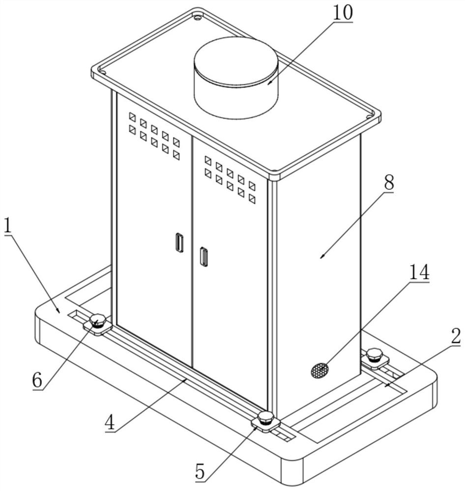
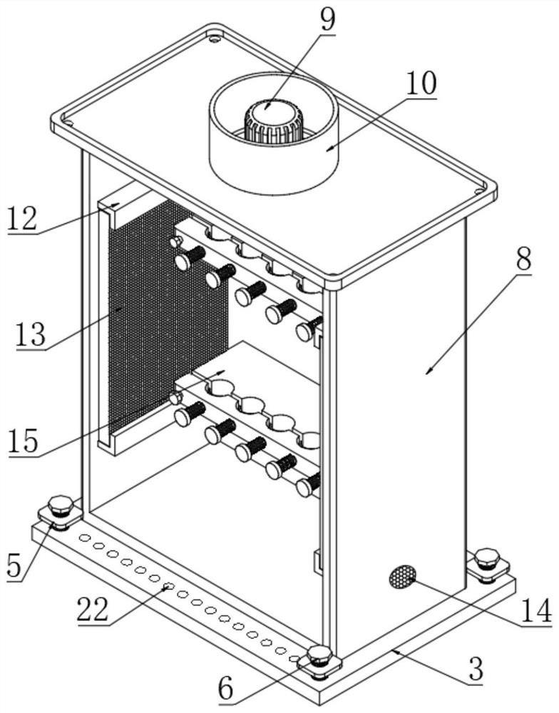
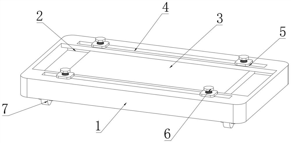
[0036] see Figure 1-4 , the present invention provides a technical solution, a multifunctional switchgear that is easy to support and adjust, including a base 1, a chute 2 is opened on the top of the base 1, a slide plate 3 is movably connected to the inner side of the chute 2, and the top of the base 1 is symmetrical on both sides A positioning groove 4 is provided, and both sides of the top of the positioning groove 4 are symmetrically connected with a fixed block 5, and the top of the fixed block 5 is movably connected with a positioning bolt 6 at the position corresponding to the positioning groove 4. There is a groove 22, the diameter of the fixing block 5 is ...


PUM


Abstract

The invention discloses a multifunctional switch cabinet convenient to support and adjust. The multifunctional switch cabinet comprises a base, wherein a sliding groove is formed in the top end of the base, a sliding plate is movably connected to the inner side of the sliding groove, positioning grooves are symmetrically formed in the two sides of the top end of the base, fixing blocks are symmetrically and movably connected to the two sides of the top end of each positioning groove, positioning bolts are movably connected to the positions, corresponding to the positioning grooves, of the top ends of the fixing blocks, and rolling wheels are installed at the four corners of the bottom end of the base. According to the invention, the structure of the multifunctional switch cabinet is scientific and reasonable, and the use the multifunctional switch cabinet is safe and convenient; when the sliding plate moves in the sliding groove, the sliding plate can drive the cabinet body to move, and after the cabinet body is placed at an appropriate position, the position of the cabinet body can be adjusted by sliding the sliding plate, so fine adjustment of the position of the cabinet body is facilitated; the top ends of the positioning grooves are connected with the fixing blocks, the positioning bolts are rotated to enable the positioning bolts to make close contact with the sliding plate, so the sliding plate is fixed, and the cabinet body is prevented from moving; and the cabinet body can be conveniently moved through the rolling wheels.

Description

technical field [0001] The invention relates to the technical field of electric equipment, in particular to a multifunctional switchgear that is convenient for support and adjustment. Background technique [0002] The switch cabinet is a kind of electrical equipment. The outside line of the switch cabinet first enters the main control switch in the cabinet, and then enters the sub-control switch. Each branch is set according to its needs. The main function of the switch cabinet is to generate, transmit, distribute and In the process of electric energy conversion, open and close, control and protect electrical equipment. The components in the switch cabinet are mainly composed of circuit breakers, isolating switches, load switches, operating mechanisms, transformers and various protection devices. They are mainly suitable for power generation. Various occasions such as factories, substations, petrochemicals, metallurgical steel rolling, light industry and textiles, factories ...

Claims


Application Information

Patent Timeline
IPC IPC(8): H02B1/30H02B1/52H02B1/32H02B1/20H02B1/56H02B1/28B08B6/00H05F3/06
CPCH02B1/303H02B1/52H02B1/32H02B1/20H02B1/565H02B1/28B08B6/00H05F3/06
Inventor 陈刚健赵海峰陈伊蕙牟旭辉郭建平
Owner 中科瑞能电气股份有限公司
Learn More