Permanent magnet, rotor assembly and motor

A technology of permanent magnets and components, applied in the direction of magnetic circuit rotating parts, magnets, magnetic objects, etc., can solve the problems of unreasonable permanent magnet structure setting, motor back EMF harmonics, cogging torque and torque ripple, and rotor Partial saturation of components and other issues

Pending Publication Date: 2021-05-28
GUANGDONG WELLING ELECTRIC MACHINE MFG +1
View PDF0 Cites 1 Cited by
  • Summary
  • Abstract
  • Description
  • Claims
  • Application Information

AI Technical Summary

Problems solved by technology

[0002] In the related art, the rotor assembly of the motor includes a rotor core and a plurality of permanent magnets. The structure of the permanent magnets is unreasonably set, and the back EMF harmonics, cogging torque and torque ripple of the motor are relatively large, and the magnetic flux leakage is serious, causing the rotor Local saturation of components is severe

Method used


Image

  • Permanent magnet, rotor assembly and motor
  • Permanent magnet, rotor assembly and motor
  • Permanent magnet, rotor assembly and motor

Examples


Embodiment 1

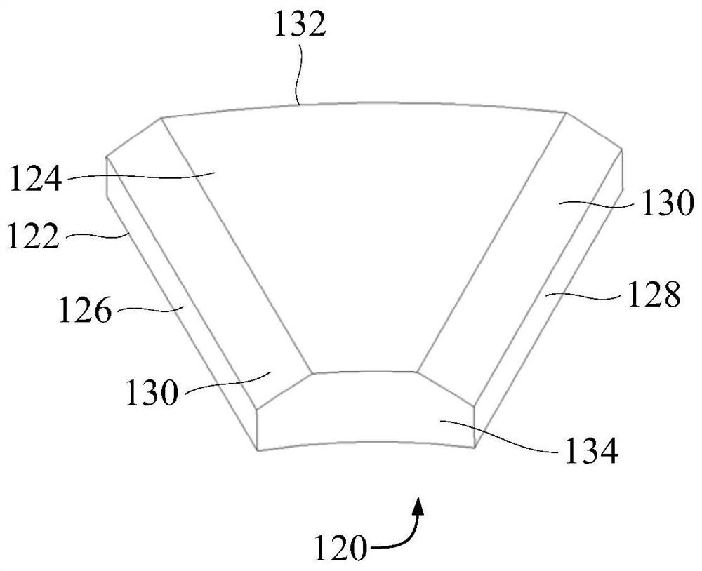
[0052] like figure 1 , figure 2 , image 3 , Figure 4 , Figure 5 , Figure 6 and Figure 7 As shown, the embodiment of the first aspect of the present invention proposes a permanent magnet 120 for the motor 200, the permanent magnet 120 includes a first end surface 122, a second end surface 124, a first side surface 126, a second side surface 128 and a transition surface 130, the first end surface 122 is opposite to the second end surface 124 and arranged at intervals, the first side surface 126 and the second side surface 128 are both located between the first end surface 122 and the second end surface 124, and the first side surface 126 and the second side surface 128 are oppositely arranged , and the first side 126 and the second side 128 are suitable for extending along the direction from the middle of the rotor core 110 of the motor 200 to the edge, the transition surface 130 is located between the first side 126 and the second end surface 124, and / or the transiti...

Embodiment 2

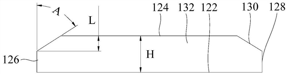
[0059] On the basis of Embodiment 1, Embodiment 2 provides a permanent magnet 120 for a motor 200. The permanent magnet 120 includes a first end surface 122, a second end surface 124, a first side surface 126, a second side surface 128 and a transition surface 130, the first end surface 122 is opposite to the second end surface 124 and arranged at intervals, the first side surface 126 and the second side surface 128 are both located between the first end surface 122 and the second end surface 124, and the first side surface 126 and the second side surface 128 are oppositely arranged , and the first side 126 and the second side 128 are suitable for extending along the direction from the middle of the rotor core 110 of the motor 200 to the edge, the transition surface 130 is located between the first side 126 and the second end surface 124, and / or the transition The surface 130 is located between the second side surface 128 and the second end surface 124 , and the distance from t...

Embodiment 3

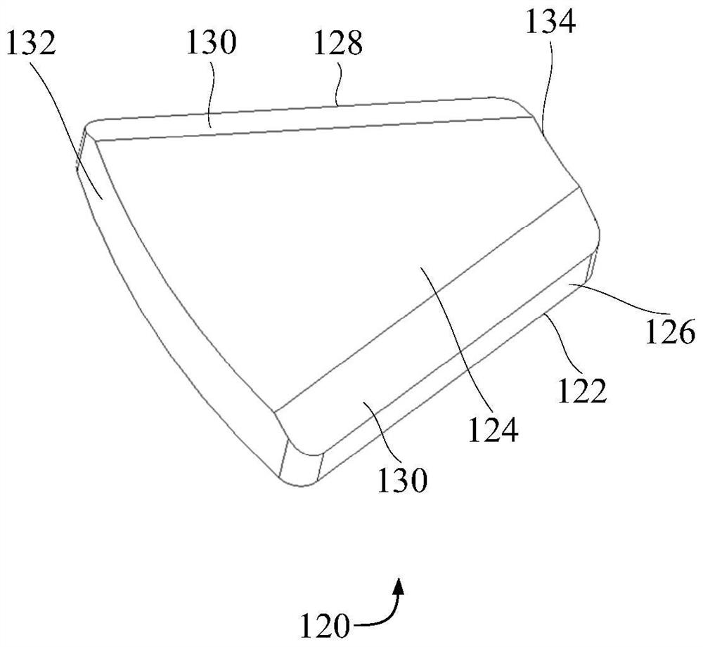
[0068] like figure 1 , figure 2 , image 3 , Figure 4 , Figure 5 , Figure 6 and Figure 7 As shown, on the basis of Embodiment 1 or Embodiment 2, Embodiment 3 provides a permanent magnet 120 for the motor 200. The permanent magnet 120 includes a first end face 122, a second end face 124, a first side face 126, The second side surface 128 and the transition surface 130, the first end surface 122 is opposite to the second end surface 124 and arranged at intervals, the first side surface 126 and the second side surface 128 are located between the first end surface 122 and the second end surface 124, the first side surface 126 Set opposite to the second side 128, and both the first side 126 and the second side 128 are adapted to extend from the middle of the rotor core 110 of the motor 200 to the edge, and the transition surface 130 is located between the first side 126 and the second end 124 and / or the transition surface 130 is located between the second side surface 12...


PUM


Abstract

The invention provides a permanent magnet, a rotor assembly and a motor. The permanent magnet is applied to the motor and comprises a first end surface, a second end surface, a first side surface, a second side surface and a transition surface, wherein the first end surface and the second end surface are opposite and are arranged at an interval; the first side surface and the second side surface are located between the first end surface and the second end surface, the first side surface and the second side surface are oppositely arranged, and the first side surface and the second side surface are suitable for extending in the direction from the middle to the edge of a rotor core of the motor; the transition surface is located between the first side surface and the second end surface, and/or the transition surface is located between the second side surface and the second end surface; the distance from the transition surface to the first end surface is less than the distance from the first end surface to the second end surface. According to the invention, reduction of back electromotive force harmonics, cogging torque and torque pulsation is facilitated.

Description

technical field [0001] The invention relates to the technical field of motors, in particular to a permanent magnet, a rotor assembly and a motor. Background technique [0002] In the related art, the rotor assembly of the motor includes a rotor core and multiple permanent magnets. The structure of the permanent magnets is unreasonably set, and the back EMF harmonics, cogging torque and torque ripple of the motor are relatively large, and the magnetic flux leakage is serious, causing the rotor The local saturation of components is severe. Contents of the invention [0003] The present invention aims to solve at least one of the technical problems existing in the prior art or related art. [0004] To this end, a first aspect of the invention proposes a permanent magnet. [0005] A second aspect of the invention proposes a rotor assembly. [0006] A third aspect of the invention proposes an electric machine. [0007] In view of this, the first aspect of the present invent...

Claims


Application Information

Patent Timeline
Patent Type & Authority Applications(China)
IPC IPC(8): H02K1/27H01F7/02
CPCH01F7/021H02K1/2793H02K2201/12
Inventor 武谷雨
Owner GUANGDONG WELLING ELECTRIC MACHINE MFG
Why Eureka
Try Eureka