
Chemical raw material deposition-removing conveying device and method

A technology of conveying device and chemical raw material, applied in the field of chemical raw material de-deposition conveying device, can solve the problems of filter screen extrusion damage, crushing of large viscous impurities, inability to control the speed of raw materials entering the valve body, etc., to avoid problems such as Long-term deposition, avoiding the effect of excessive feeding speed

Active Publication Date: 2021-06-01
NANYANG INST OF TECH
View PDF6 Cites 0 Cited by
  • Summary
  • Abstract
  • Description
  • Claims
  • Application Information

AI Technical Summary

Problems solved by technology

[0005] 1. Although this solution can avoid the phenomenon of deposition by stirring, it cannot crush large viscous impurities. Long-term deposition will often block the filter screen
[0006] 2. And it is impossible to control the speed of raw materials entering the valve body. If the feeding speed is too fast, it will cause excessive extrusion damage to the filter screen

Method used


Image

  • Chemical raw material deposition-removing conveying device and method
  • Chemical raw material deposition-removing conveying device and method
  • Chemical raw material deposition-removing conveying device and method

Examples


Embodiment Construction

[0053]The technical solutions of the present invention will be further described below with reference to the accompanying drawings.

[0054]The drawings are for exemplary description, which is merely a schematic diagram, rather than the experiment, and is not to be understood to be in this patent; in order to better illustrate the embodiments of the invention, there will be omitted, Enlarge or shrink does not mean the size of the actual product.

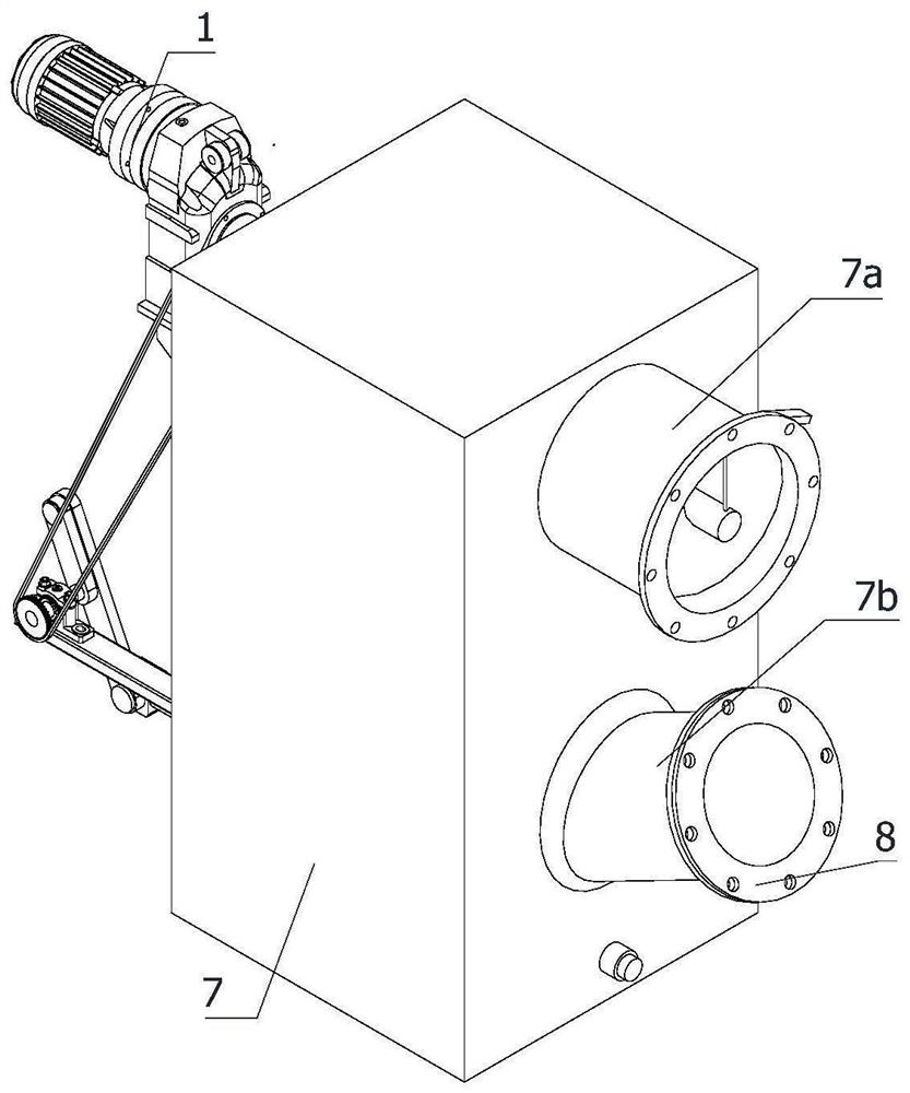
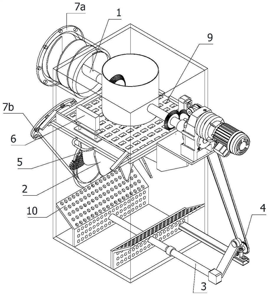
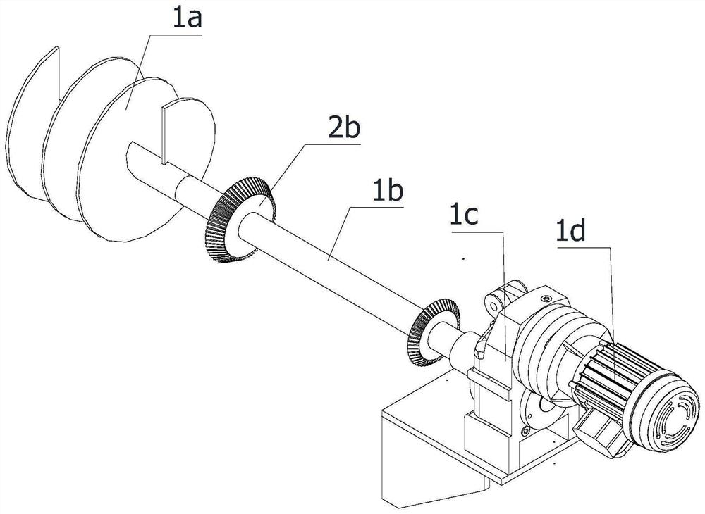
[0055]ReferFigure 1 to 9A chemical raw material deposited transport device, including a flow rate control mechanism 1, an axis push mechanism 2, a reciprocating pressing mechanism 3, a cleaning mechanism 5, a blocking gate 6, a valve body 7, a filter tub 8, a square filter plate 9 and The two bending plate 10, the valve body 7 is fixed to the installation conduit, and the feed tube 7a and the discharge tube 7b are provided on the valve body 7, and the feed tube 7a is fixedly connected to the pipe opening, the discharge tube 7b and The feed port ...


PUM


Abstract

The invention relates to the field of chemical raw material conveying, in particular to a chemical raw material deposition-removing conveying device and method. The chemical raw material deposition-removing conveying device comprises a flow speed control mechanism, an axis pushing mechanism, a reciprocating extrusion mechanism, a cleaning mechanism, a blocking gate, a valve body, a filtering barrel, a square filtering plate and two bent filtering plates. According to the chemical raw material deposition-removing conveying device and method, through combination of a transmission mechanism, the axis pushing mechanism and the reciprocating extrusion mechanism, large viscous impurities are crushed in time, long-term deposition is avoided, blockage of a filter screen is avoided; and through forward work and reverse work of combination of the flow speed control mechanism and the axis pushing mechanism, the speed of raw materials entering the valve body is controlled, and excessive extrusion damage to the filter screen caused by too high feeding speed is avoided.

Description

Technical field[0001]The present invention relates to the field of chemical raw materials, and more particularly to a chemical raw material deposition delivery device and method.Background technique[0002]The Y-shaped filter is an indispensable filtration device of the pipe system of the transport medium. The Y-shaped filter is typically mounted on the pressure reducing valve, a pressure relief valve, a fixed water valve or other device, which is used to remove impurities in the medium. To protect the normally used of valves and equipment. When filtered on impurities, the impurities will often leave within the filter, and the large block of viscous impurities cannot be cleaned, and it is often caused to block the filter, so that the raw material cannot be transported, and the feed speed is too fast. The filter is crushed.[0003]my country's patent application number: CN20191096758.0; Open filter basket extraction reverse Y-shaped filter, the structure design of the present invention i...

Claims


Application Information

Patent Timeline
Patent Type & Authority Applications(China)
IPC IPC(8): B01D29/56B01D29/82B01D29/86B01D29/60
CPCB01D29/56B01D29/82B01D29/86B01D29/603
Inventor 叶红勇刘玉洁曹英寒左广玲李入林吴可量
Owner NANYANG INST OF TECH
Learn More