Rice impurity removing equipment
A technology of impurity and rice, applied in the field of rice impurity removal equipment, can solve the problems of laborious and time-consuming, and achieve the effect of high work efficiency and convenient collection
- Summary
- Abstract
- Description
- Claims
- Application Information
AI Technical Summary
Problems solved by technology
Method used
Image

Examples
Embodiment 1
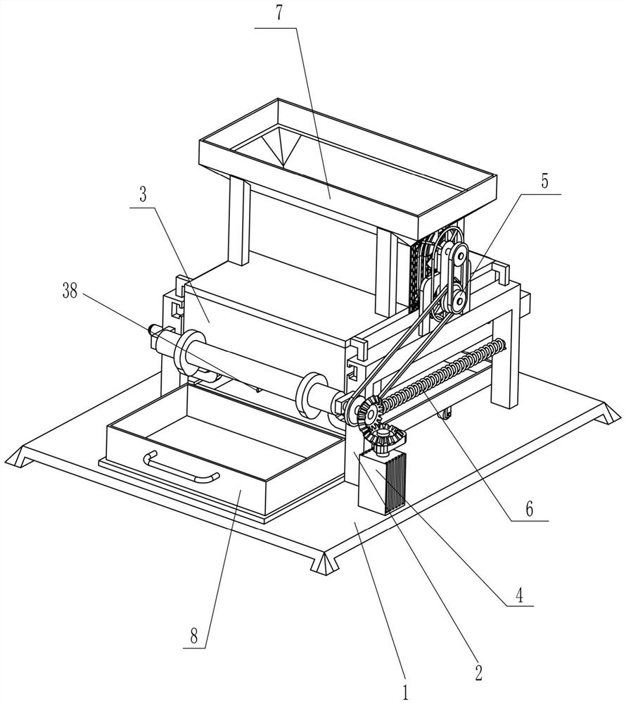
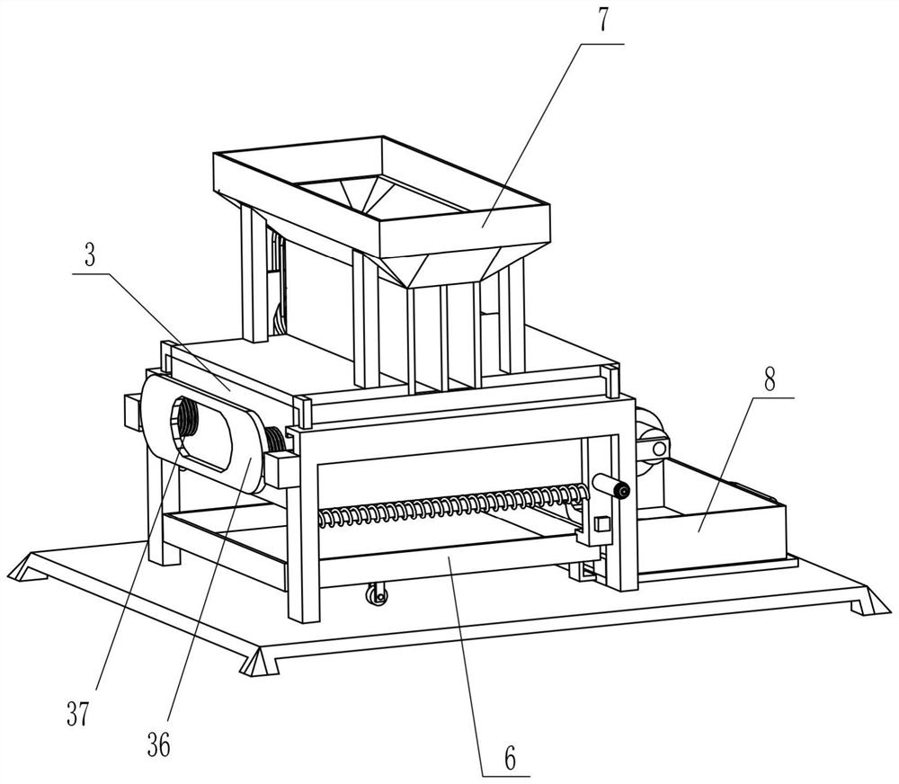
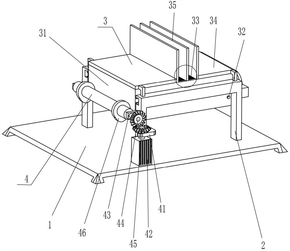
[0028] A rice impurity removal device, such as figure 1 , figure 2 , image 3 and Figure 8 As shown, it includes a base 1, a slotted support frame 2, a filter mechanism 3, and a drive mechanism 4. The slotted support frame 2 is fixedly connected to the front and rear symmetrically on the right side of the top of the base 1, and the slotted support frame 2 is provided with a filter mechanism 3. A drive mechanism 4 is provided between the base 1 and the slotted support frame 2 , and the drive mechanism 4 cooperates with the filter mechanism 3 .
[0029] The filter mechanism 3 includes a rectangular frame 31, a hinged rod 32, a filter screen 33, a first fixed plate 34, a magnetic plate 35, a first special-shaped plate 36 and a first spring 37, between the front and rear sides of the slotted support frame 2 The sliding type is provided with a rectangular frame 31, and the rotating type is provided with a hinged rod 32 on the lower right side of the rectangular frame 31. The m...
Embodiment 2
[0033] On the basis of Example 1, such as figure 1 , Figure 4 and Figure 5 As shown, it also includes a foreign removal mechanism 5, and the foreign removal mechanism 5 includes a second special-shaped plate 51, a second rotating shaft 52, a first transmission assembly 53, a third rotating shaft 54, a second transmission assembly 55, fan blades 56, protection Cover 57 and protective net 58, the second special-shaped plate 51 is fixedly connected in the middle of the slotted support frame 2 top in the front, and the second special-shaped plate 51 middle part lower side is rotatably provided with second rotating shaft 52, and the second rotating shaft 52 anterior circumferential direction and The first transmission assembly 53 is connected between the front circumferential direction of the first rotating shaft 44, and the upper side of the middle part of the second special-shaped plate 51 is rotatably provided with a third rotating shaft 54, between the front circumferential ...
Embodiment 3
[0038] On the basis of embodiment 1 and embodiment 2, such as figure 1 , figure 2 , Figure 6 and Figure 7 As shown, it also includes a material guide device 7, and the material guide device 7 includes a second fixed block 71, a material guide frame 72 and a tapered frame 73, and the inner tops of the first fixed plates 34 on the left and right sides are symmetrically fixed to the front and back. The second fixed block 71, the object guide frame 72 is fixedly connected between the four second fixed blocks 71, and the top of the object guide frame 72 is a tapered frame 73.
[0039] Also includes collection device 8, and collection device 8 includes the 3rd fixed block 81, collection frame 82 and handle 83, and the 3rd fixed block 81 is affixed symmetrically before and after the right side of the second fixed plate 68 top, and the second fixed plate 68 A collection frame 82 is placed on the upper slide, and a handle 83 is affixed to the middle part of the outer left side of...
PUM
 Abstract
Description
Claims
Application Information
 - R&D
- Intellectual Property
- Life Sciences
- Materials
- Tech Scout
- Unparalleled Data Quality
- Higher Quality Content
- 60% Fewer Hallucinations
Browse by: Latest US Patents, China's latest patents, Technical Efficacy Thesaurus, Application Domain, Technology Topic, Popular Technical Reports.
© 2025 PatSnap. All rights reserved.Legal|Privacy policy|Modern Slavery Act Transparency Statement|Sitemap|About US| Contact US: help@patsnap.com