Wrench polishing equipment for hardware

A wrench and equipment technology, applied in the field of hardware wrench polishing equipment, can solve problems such as the influence of the lifting height of the support plate, the jamming of the push rod and the thread groove, and the distance between the wrench and the polisher, etc. The effect of little resistance

Inactive Publication Date: 2021-06-01
上海曰茶贸易有限公司
View PDF0 Cites 3 Cited by
  • Summary
  • Abstract
  • Description
  • Claims
  • Application Information

AI Technical Summary

Problems solved by technology

[0002] Use a polishing machine to polish the wrench used for hardware, place the wrench on the support plate of the polishing table, control the movement of the push rod and the thread groove to drive the support plate to rise, so that the distance between the wrench and the polisher is shortened, and the distance between the polisher and the polisher is controlled. Wrench polishing; in the prior art, when a polishing machine is used to polish a wrench for hardware, the metal debris produced by the polishing of the outer wall of the wrench is splashed on the surface of the polishing table by the throwing force of the polisher, and some parts are easy to follow the thread of the polishing table. The gap between the groove and the push rod enters, causing the push rod to get stuck when the thread is matched with the thread groove, which affects the lifting height of the support plate, and cannot normally drive the wrench to cooperate with the polisher for polishing

Method used


Image

  • Wrench polishing equipment for hardware
  • Wrench polishing equipment for hardware
  • Wrench polishing equipment for hardware

Examples


Embodiment 1

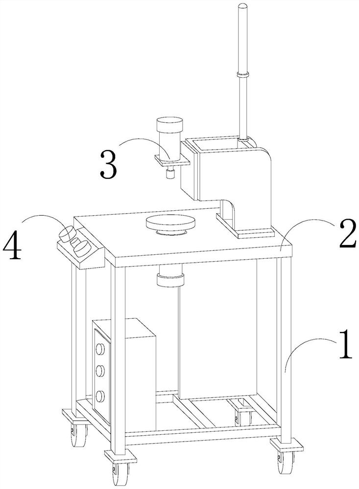
[0027] as attached figure 1 To attach Figure 5 Shown:

[0028] The invention provides a wrench polishing equipment for hardware, the structure of which includes a support frame 1, a polishing table 2, a polisher 3, and a controller 4, the polishing table 2 is horizontally welded on the top of the support frame 1, and the polisher 3 is installed on The top of the polishing table 2, the controller 4 is arranged in the middle of the front of the polishing table 2.

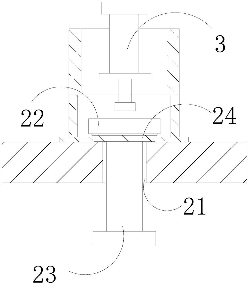
[0029] The polishing table 2 is provided with a thread groove 21, a support plate 22, a push rod 23, and a blocking mechanism 24. The thread groove 21 runs through the upper and lower surfaces of the middle part of the polishing table 2, and the support plate 22 is located above the polishing table 2. The rod 23 is threadedly matched with the thread groove 21 , and the top is connected to the bottom surface of the support plate 22 , the blocking mechanism 24 is fixed on the bottom of the support plate 22 and wrappe...

Embodiment 2

[0036] as attached Figure 6to attach Figure 8 Shown:

[0037] Wherein, the contact block d4 is provided with a movable groove e1, a rotating ring e2, a matching plate e3, and a stacking cavity e4, the movable groove e1 is recessed on the top of the contact block d4, and the rotating ring e2 is connected and installed inside the movable groove e1, The matching plate e3 is set on the inner wall of the movable groove e1, and is movably matched with the rotating ring e2. The accumulation chamber e4 is set at the inner bottom of the contact block d4 and communicates with the movable groove e1. The upper surface of the matching plate e3 is concave-convex The uneven surface can increase the friction between the matching plate e3 and the outer wall of the rotating ring e2, and evenly remove the debris on the outer wall of the rotating ring e2. There are three rotating rings e2, which is conducive to the continuous contact between the rotating ring e2 and the exhaust port s2 The in...


PUM


Abstract

The invention discloses wrench polishing equipment for hardware. The wrench polishing equipment structurally comprises a supporting frame, a polishing table, a polisher and a controller, the polishing table is horizontally welded to the top of the supporting frame, the polisher is installed at the top of the polishing table, the controller is arranged in the middle of the front face of the polishing table, due to the fact that chippings easily enter along a gap between a threaded groove of the polishing table and a push rod, the chippings are blocked through a telescopic pipe of a blocking mechanism, the situation that the chippings enters the gap between the threaded groove of the polishing table and the push rod can be reduced, the phenomenon that the push rod is clamped when being in threaded fit with the threaded groove is reduced, free lifting of a supporting plate is facilitated, a wrench is normally driven to be matched with the polisher for polishing treatment, part of chippings are easily retained on the inner wall, close to the outer end, of an exhaust port, contact blocks make contact with the inner wall of the exhaust port, the chippings on the inner wall of the exhaust port are removed through a removing plate, resistance of the chippings to a clamping plate can be reduced, and the back-and-forth moving speed of the clamping plate in the exhaust port is increased.

Description

technical field [0001] The invention belongs to the field of surface polishing processing in hardware production, and more specifically relates to a wrench polishing equipment for hardware. Background technique [0002] Use a polishing machine to polish the wrench used for hardware, place the wrench on the support plate of the polishing table, control the movement of the push rod and the thread groove to drive the support plate to rise, so that the distance between the wrench and the polisher is shortened, and the distance between the polisher and the polisher is controlled. Wrench polishing; in the prior art, when a polishing machine is used to polish a wrench for hardware, the metal debris produced by the polishing of the outer wall of the wrench is splashed on the surface of the polishing table by the throwing force of the polisher, and some parts are easy to follow the thread of the polishing table. The gap between the groove and the push rod enters, causing the push rod...

Claims


Application Information

Patent Timeline
Patent Type & Authority Applications(China)
IPC IPC(8): B24B29/02B24B41/02B24B51/00B24B55/06
CPCB24B29/02B24B41/02B24B51/00B24B55/06
Inventor 王辉
Owner 上海曰茶贸易有限公司
Why Eureka
Try Eureka