Rail type tower crane and hoisting method thereof
A track-type, tower crane technology, applied in cleaning methods and appliances, chemical instruments and methods, cleaning methods using tools, etc., can solve the problem that workers' personal safety cannot be guaranteed, smooth sliding cannot be achieved, and pulleys are easy to get stuck, etc. problems, to avoid midway jamming, increase sliding, and achieve the effect of lubricity
- Summary
- Abstract
- Description
- Claims
- Application Information
AI Technical Summary
Problems solved by technology
Method used
Image

Examples
Embodiment 1
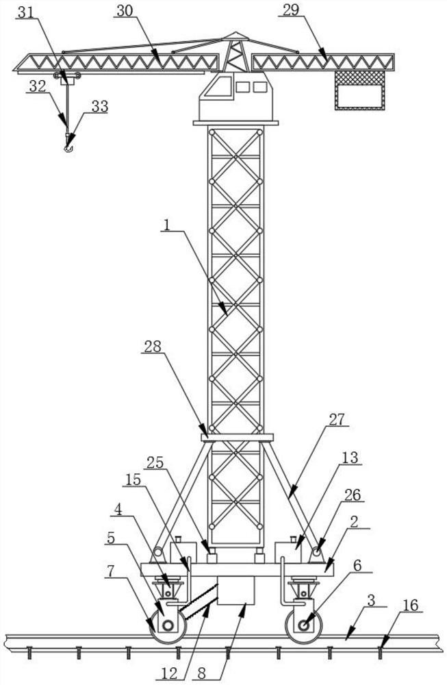
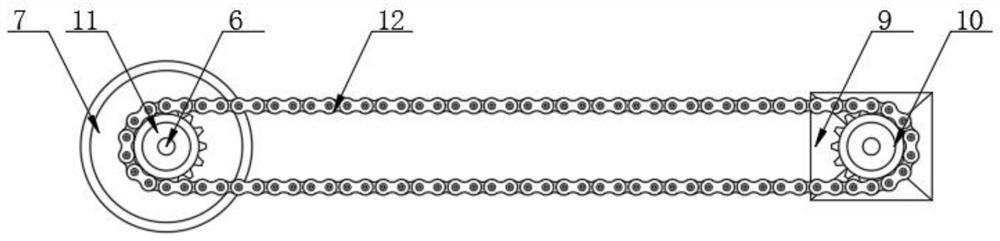
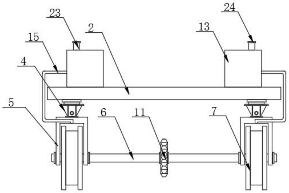
[0029] see Figure 1-6 , the present invention provides a technical solution: a track-type tower crane, including a tower body 1, a bottom plate 2 and a slide rail 3, both sides of the bottom of the bottom plate 2 are fixedly connected with a mounting seat 4, and the bottom of the mounting seat 4 is fixedly connected with a U-shaped plate 5, two opposite sides of U-shaped plate 5 are rotationally connected with fixed rod 6, and both sides of the surface of fixed rod 6 are fixedly connected with pulley 7, and the bottom of base plate 2 is fixedly connected with protective box 8, and The bottom of the inner wall of the protection box 8 is fixedly connected with a motor 9, and the motor 9 is a servo motor. The surface of the sprocket 10 and the second sprocket 11 is connected by a chain 12, and both sides of the top of the bottom plate 2 are fixedly connected with a box body 13, and the bottom inside the box body 13 is fixedly connected with an oil well pump 14, and the oil well ...
Embodiment 2
[0034] This embodiment is a further improvement of the previous embodiment, please refer to Figure 1-6, the present invention provides a technical solution: a track-type tower crane, including a tower body 1, a bottom plate 2 and a slide rail 3, both sides of the bottom of the bottom plate 2 are fixedly connected with a mounting seat 4, and the bottom of the mounting seat 4 is fixedly connected with a U-shaped plate 5, two opposite sides of U-shaped plate 5 are rotationally connected with fixed rod 6, and both sides of the surface of fixed rod 6 are fixedly connected with pulley 7, and the bottom of base plate 2 is fixedly connected with protective box 8, and The bottom of the protection box 8 inner wall is fixedly connected with a motor 9, the output end of the motor 9 is fixedly connected with a first sprocket 10, and the middle part of the surface of the fixed rod 6 is fixedly connected with a second sprocket 11, and the first sprocket 10 is connected with the second sprock...
PUM
 Abstract
Description
Claims
Application Information