
A fluid damper for impact test device

A technology of fluid damper and impact test, which is applied in the direction of impact test, measuring device, liquid shock absorber, etc., to achieve the effect of convenient implementation, simple structure and high reliability

Active Publication Date: 2022-03-22
SHANGHAI JIAO TONG UNIV
View PDF11 Cites 0 Cited by
  • Summary
  • Abstract
  • Description
  • Claims
  • Application Information

AI Technical Summary

Problems solved by technology

More importantly, the use of servo valves also has problems such as the reliability of the control system under shock conditions.

Method used


Image

  • A fluid damper for impact test device
  • A fluid damper for impact test device

Examples


Embodiment Construction

[0043] The implementation of the present invention will be illustrated by specific specific examples below, and those skilled in the art can easily understand other advantages and effects of the present invention from the content disclosed in this specification. Although the description of the present invention will be presented in conjunction with a preferred embodiment, it does not mean that the features of the invention are limited to this embodiment. On the contrary, the purpose of introducing the invention in conjunction with the embodiments is to cover other options or modifications that may be extended based on the claims of the present invention. The following description contains numerous specific details in order to provide a thorough understanding of the present invention. The invention may also be practiced without these details. Also, some specific details will be omitted from the description in order to avoid obscuring or obscuring the gist of the present invent...


PUM


Abstract

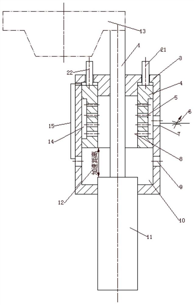
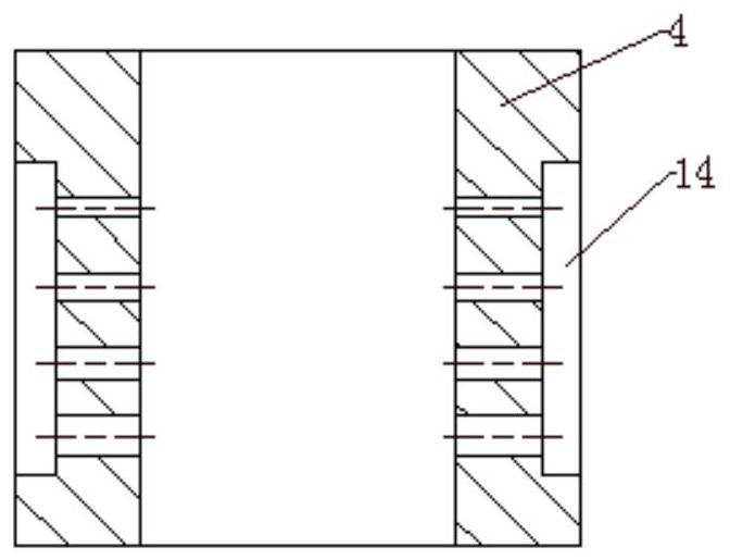
The invention discloses a fluid damper for an impact test device, which is characterized in that it includes a cylinder, a piston, a piston rod, a valve sleeve and an adjustment mechanism; wherein the piston is connected to the bottom of the piston rod, and the top of the piston rod extends To the outside of the cylinder and connected to the impact table, the piston is installed in the cylinder, and can move along the length of the cylinder, the adjustment mechanism is connected with the valve sleeve, the valve sleeve is installed on the inner wall of the cylinder, and can move along the length of the cylinder Axial movement, an annular groove is provided on the outer wall of the valve sleeve, and several radial holes are opened on the annular groove. The radial holes are arranged at intervals along the axial direction of the valve sleeve. The inner diameter of the valve sleeve is slightly larger than the outer diameter of the piston. , an annular gap is formed between the two; an adjustable valve port is formed between the lower end surface of the valve sleeve and the upper end surface of the piston.

Description

Technical field: [0001] The invention relates to the technical field of impact testing, in particular to a cylinder-valve integrated fluid damper with adjustable valve port opening and fluid outflow area. Background technique: [0002] Before being used in aerospace, ship equipment, anti-terrorist attack equipment, etc., shock resistance tests are required to evaluate its shock resistance performance. [0003] On the one hand, with the continuous improvement of safety awareness, the requirements for the impact resistance of equipment are becoming more and more stringent, and components and complete machines need to be assessed separately for impact performance. [0004] On the other hand, with the needs of equipment development, the power of equipment is getting higher and higher, and the operating speed is getting higher and higher, and the impact environment that needs to be endured is becoming more and more severe. This puts forward higher requirements on the performance...

Claims


Application Information

Patent Timeline
Patent Type & Authority Patents(China)
IPC IPC(8): F16F9/19F16F9/32F16F9/346G01M7/08
CPCF16F9/19F16F9/3207F16F9/3235F16F9/346G01M7/08
Inventor 焦素娟华宏星
Owner SHANGHAI JIAO TONG UNIV
Learn More