
Combustor and gas cooker

A technology for burners and gas passages, applied in the direction of burners, gas fuel burners, combustion methods, etc., can solve the problems of wasting gas, insufficient combustion, poor mixing effect, etc., and achieve simple and reasonable structure, full combustion, and good The effect of mixing effects

Pending Publication Date: 2021-06-01
SUPERMAN ZHONGSHAN ELECTRIC APPLIANCES CO LTD
View PDF16 Cites 0 Cited by
  • Summary
  • Abstract
  • Description
  • Claims
  • Application Information

AI Technical Summary

Problems solved by technology

The structure of the burner often affects the utilization rate of the gas. The current burner generally only has one air injection at the inlet, and the structure of the gas flow channel is often relatively simple. The mixing effect in the flow channel is poor, which may cause insufficient combustion when the output is burned on the fire cover. The utilization rate of gas is not high, which wastes gas and is not conducive to the safety and health of users.

Method used


Image

  • Combustor and gas cooker
  • Combustor and gas cooker
  • Combustor and gas cooker

Examples


Embodiment Construction

[0029] Embodiments of the present invention are described in detail below, examples of which are shown in the drawings, wherein the same or similar reference numerals designate the same or similar elements or elements having the same or similar functions throughout. The embodiments described below by referring to the figures are exemplary only for explaining the present invention and should not be construed as limiting the present invention.

[0030] In the description of the present invention, it should be understood that if it involves orientation descriptions, for example, the orientation or positional relationship indicated by up, down, etc. is based on the orientation or positional relationship shown in the drawings, it is only for the convenience of describing the present invention and simplifying the Describes, but does not indicate or imply that the device or element referred to must have a specific orientation, be constructed in a specific orientation, and operate in a...


PUM


Abstract

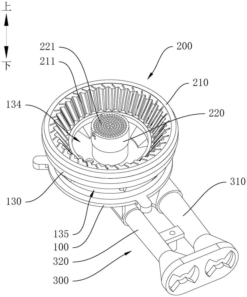
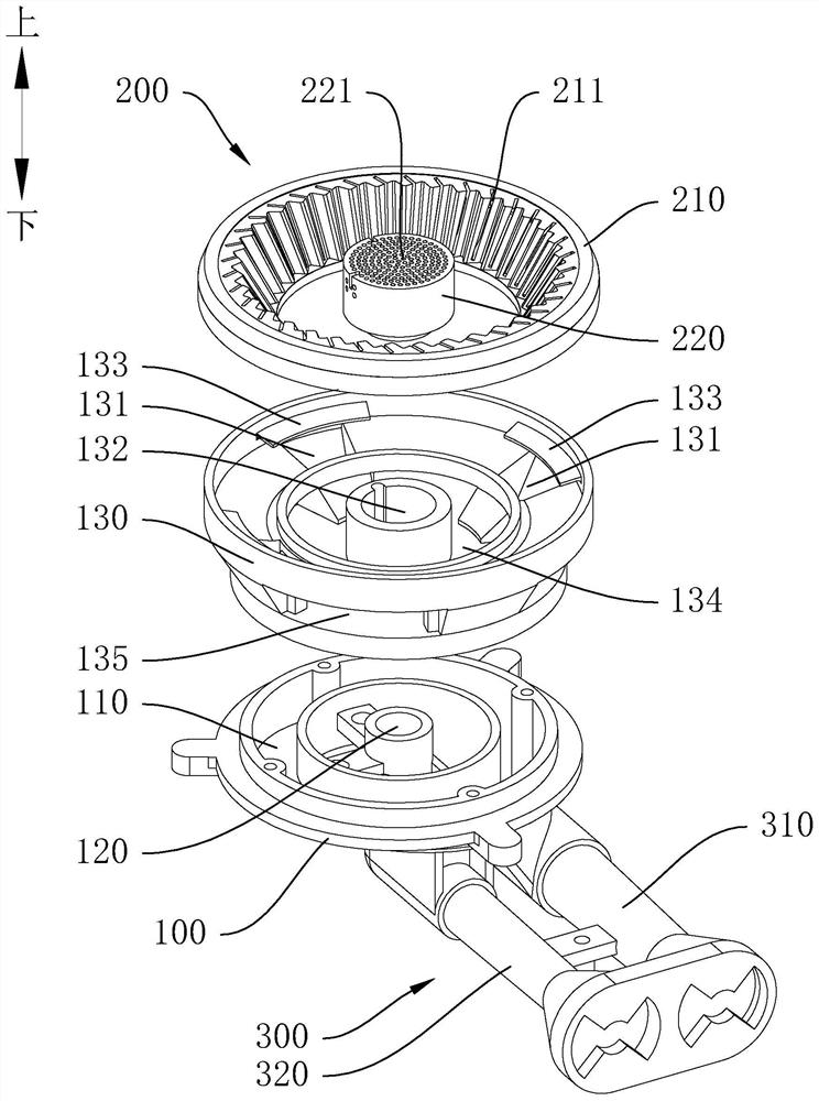
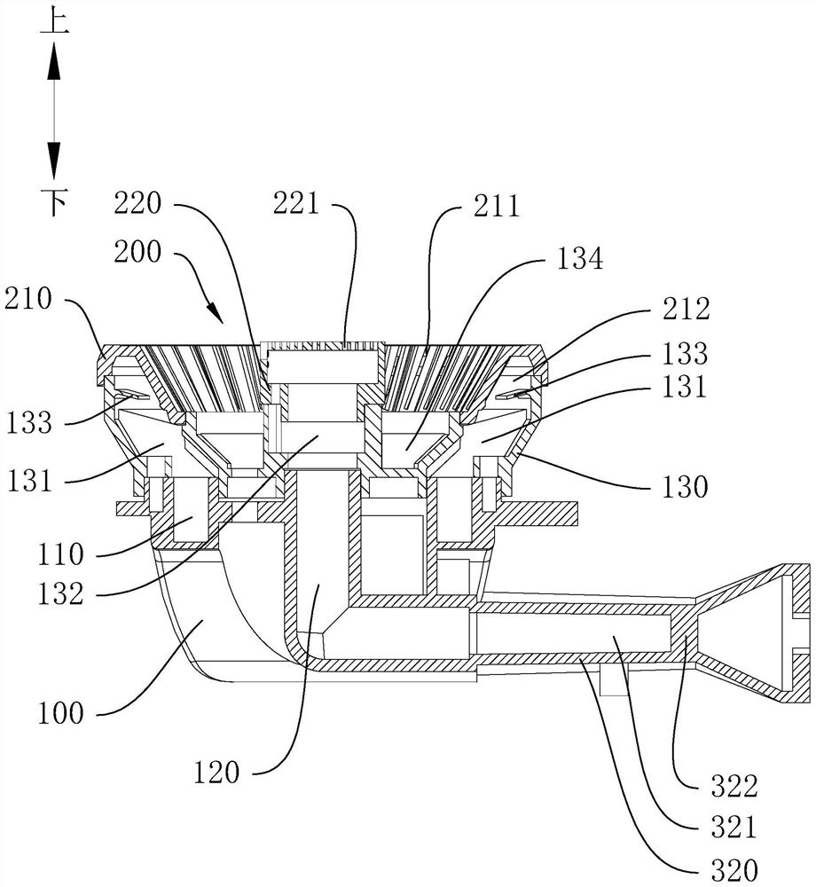
The invention discloses a combustor and a gas cooker. The gas cooker comprises the combustor; the combustor comprises a furnace end, a fire cover assembly and an injection pipe set; a first gas channel is formed in the furnace end; the fire cover assembly is connected to the furnace end; a first gas outlet hole communicating with the first gas channel is formed in the fire cover assembly; the injection pipe set is connected to the furnace end; the injection pipe set comprises a first injection pipe; the first injection pipe is provided with a first injection channel communicating with the first fuel gas channel; a first flow guide part is arranged in the first injection channel and is in a sheet shape; and the two side faces of the first flow guide part are outwards-protruding arc-shaped curved surfaces. The combustor and the gas cooker provided by the invention are simple and reasonable in structure, and fuel gas and injected air can be well mixed, so that full combustion of the fuel gas can be achieved, and the utilization rate of the fuel gas is increased.

Description

technical field [0001] The invention relates to the field of gas equipment, in particular to a burner and a gas cooker. Background technique [0002] Gas cooker is one of the common gas equipment in contemporary people's life. Among them, the burner is the main part of the gas cooker. The air intake end of the injector introduces and mixes with it, then enters the burner and outputs to the fire cover to be ignited by the ignition needle for combustion. The structure of the burner often affects the utilization rate of the gas. The current burner generally only has one air injection at the inlet, and the structure of the gas flow channel is often relatively simple. The mixing effect in the flow channel is poor, which may cause insufficient combustion when it is output to the burner for combustion. The utilization rate of gas is not high, which wastes gas and is not conducive to the safety and health of users. Contents of the invention [0003] The present invention aims to...

Claims


Application Information

Patent Timeline
Patent Type & Authority Applications(China)
IPC IPC(8): F23D14/04F23D14/46F23D14/64F23D14/70F24C3/08
CPCF23D14/04F23D14/46F23D14/64F23D14/70F24C3/085F23D2900/14062
Inventor 罗子健罗先明蒲平
Owner SUPERMAN ZHONGSHAN ELECTRIC APPLIANCES CO LTD
Learn More