Contact network flaw detection system

A technology of flaw detection and catenary, which is applied in the direction of radio wave measurement system, signal transmission system, satellite radio beacon positioning system, etc., can solve the problems of inability to detect the internal damage of the catenary, catenary flaw detection, etc.

Active Publication Date: 2021-06-01
EAST CHINA JIAOTONG UNIVERSITY
View PDF9 Cites 2 Cited by
  • Summary
  • Abstract
  • Description
  • Claims
  • Application Information

AI Technical Summary

Problems solved by technology

These methods can detect the degree of wear on the outer surface of the contact wire, but cannot detect the interior of the contact wire, and cannot detect the internal damage of the contact wire

Method used


Image

  • Contact network flaw detection system
  • Contact network flaw detection system
  • Contact network flaw detection system

Examples


Embodiment Construction

[0020] The present invention will be described in further detail below in conjunction with the embodiments and with reference to the accompanying drawings.

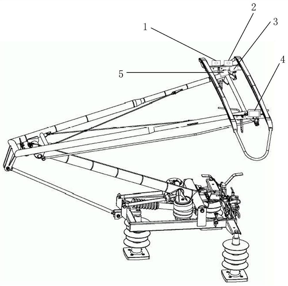
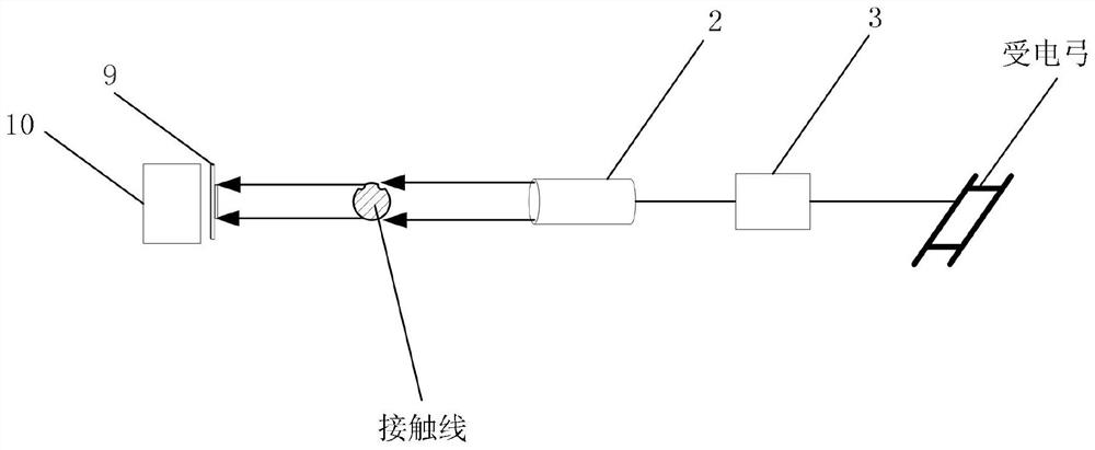
[0021] see Figure 1 to Figure 4 , a catenary flaw detection system in the present invention includes a laser imaging radar 1 , an X-ray emitter 2 , a booster 3 , an X-ray receiver 4 , and a control circuit board 5 .

[0022] Such as figure 1 As shown, the laser imaging radar 1, X-ray transmitter 2, booster 3, and control circuit board 5 are installed on one end of the pantograph head, and the X-ray receiver 4 is installed on the other end of the pantograph head At one end, the laser imaging radar 1 emits a laser beam to the contact line for scanning, and receives the laser radiation reflected by the contact line to generate continuous analog signals, which are restored to real-time contact line images, and these analog signals are converted in the control circuit board 5 Calculate the height of the contact line in the ...


PUM


Abstract

The invention discloses a contact network flaw detection system, which comprises a laser imaging radar, an X-ray emitter, a voltage booster, an X-ray receiver and a control circuit board, wherein the laser imaging radar emits a laser beam to a contact line for scanning, laser radiation reflected by the contact line is received to generate continuous analog signals, the continuous analog signals are restored into a real-time contact line image, the height of the contact line in the horizontal direction is calculated after the analog signals are converted into digital signals in a control circuit board, then the abrasion degree of the outer surface of the contact line is determined, the electric energy obtained by a pantograph on the contact line is boosted by the booster and then is supplied to the X-ray emitter, the X-ray emitter and the X-ray receiver form the X-ray flaw detector, flaw detection is conducted on the interior of the contact line, the damaged contact line is positioned through a Beidou positioning module, and then detected information is transmitted to a monitoring center of related departments of a railway and a train running on the line in real time through a 5G communication technology.

Description

technical field [0001] The invention relates to the field of catenary flaw detection, in particular to a catenary flaw detection system. Background technique [0002] The contact wire is a high-voltage pre-tensioned wire erected along the electrified railway, and its material is usually pure copper, copper-silver alloy, copper-magnesium alloy and copper-tin alloy. During the operation of the train, the pantograph sliding plate installed on the top of the locomotive slides through contact with the contact wire, and transmits the obtained electric energy to the power supply system of the electric locomotive as the driving force for its high-speed operation. This process is also called receiving current. The quality and stability of the flow directly determine whether the electric locomotive can run safely and reliably. The pantograph-catenary system composed of pantograph and contact wire constitutes an important power supply system of electrified railway. [0003] The caten...

Claims


Application Information

Patent Timeline
Patent Type & Authority Applications(China)
IPC IPC(8): G01N23/04G01N21/88G01S17/89G01S19/14G08C17/02
CPCG01N23/04G01N21/8851G01S17/89G01S19/14G08C17/02G01N2021/8887G01S17/88G01S17/42G01N23/18G01N2223/646G01N23/083
Inventor 胡军黄裕高云博郭成成钟琪赖亚昕
Owner EAST CHINA JIAOTONG UNIVERSITY
Why Eureka
Try Eureka