Power distribution cabinet

A power distribution cabinet and main body technology, applied in substation/power distribution device housing, electrical components, substation/switch layout details, etc., can solve the problems of dust in power facilities, unfavorable ventilation, difficulty in quickly finding cables, easy to absorb dust, etc. , to achieve the effect of easy to find lines, easy to organize and store, and conducive to circulation

Active Publication Date: 2021-06-01
广东兆兴机电有限公司
View PDF4 Cites 0 Cited by
  • Summary
  • Abstract
  • Description
  • Claims
  • Application Information

AI Technical Summary

Problems solved by technology

[0006] Aiming at the deficiencies of the prior art, the present invention provides a power distribution cabinet, which solves the problem that the surface of the power facilities inside the power distribution cabinet is usually easy to absorb dust, and the dust attached to the power facilities is not conducive to ventilation, and is prone to short circuit and other faults. There are too many and messy internal lines, making it difficult to quickly find the location of the corresponding cable

Method used


Image

  • Power distribution cabinet
  • Power distribution cabinet
  • Power distribution cabinet

Examples


Embodiment 1

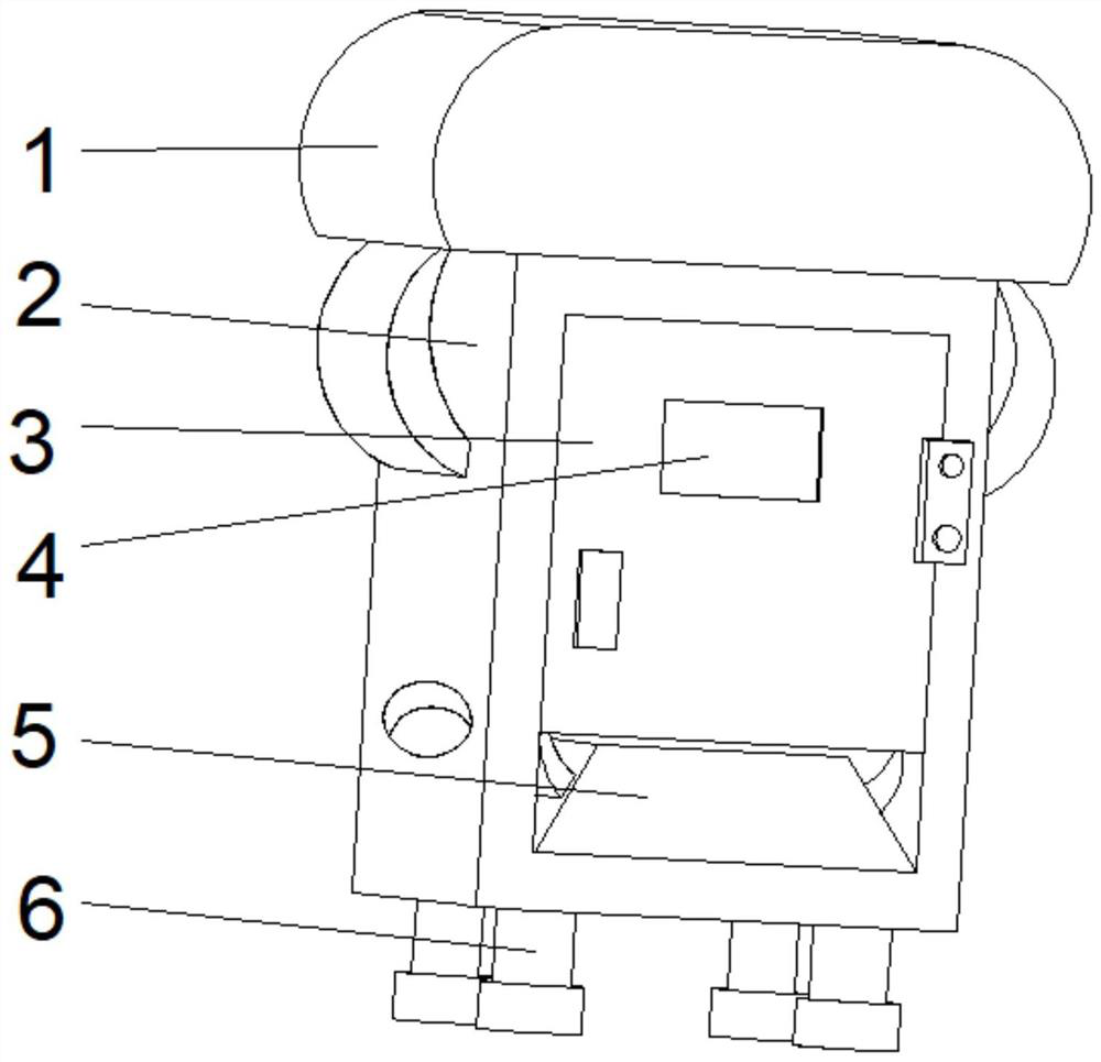
[0033] see Figure 1-2 , the present invention provides a technical solution: a power distribution cabinet, including a main body 2, the top of the main body 2 is fixedly connected with a top cover 1, and the middle positions on both sides of the bottom of the top cover 1 are fixedly connected with the main body 2, and the bottom of the main body 2 Both sides are fixedly connected with a support 6, the front top of the main body 1 is provided with a box door 3, the middle position of the front top of the box door 3 is fixedly connected with an observation window 4, and the bottom of the inner cavity of the main body 2 is fixedly connected with a processing device 5.

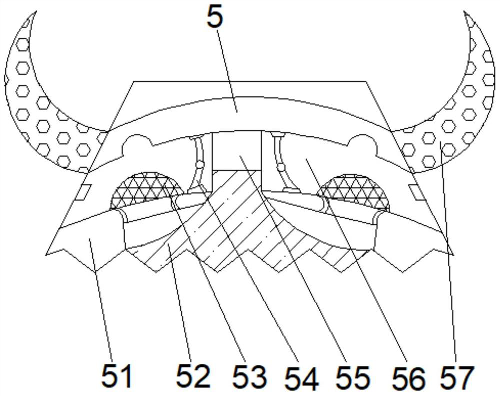
[0034] Wherein, the processing device 5 includes a collecting plate 56, the middle part of the outer wall on both sides of the collecting plate 56 is fixedly connected with a contact plate 57, the middle part of the inner wall on both sides of the collecting plate 56 is fixedly connected with a processing mechanis...

Embodiment 2

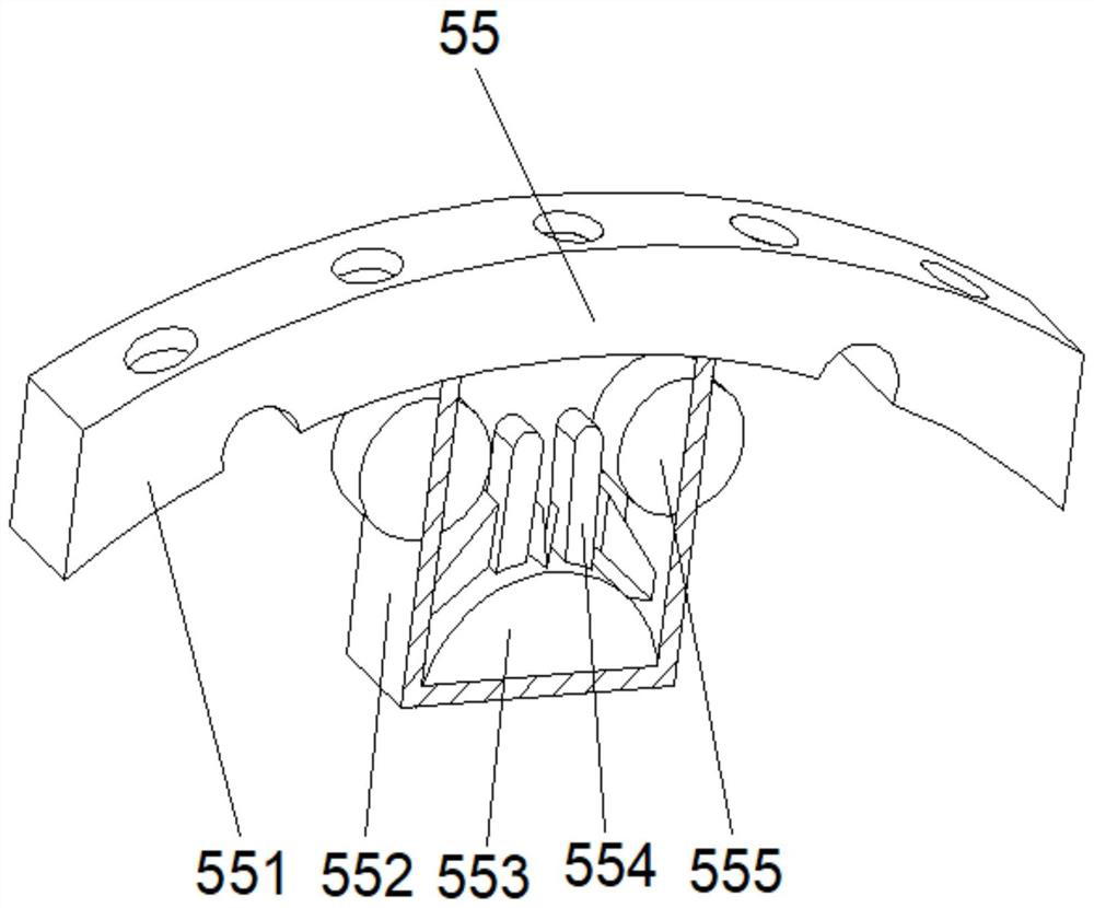
[0037] see Figure 1-4 On the basis of Embodiment 1, the present invention provides a technical solution: the processing mechanism 55 includes a vertical block 552, the top of the vertical block 552 is fixedly connected with a guide block 551, and the top of the outer walls of both sides of the vertical block 552 is provided with sliders 555 The outer surface of the slider 555 runs through the vertical block 552 and extends to the inside of the vertical block 553. The bottom of the inner cavity of the vertical block 552 is fixedly connected with a collection box 553, and the middle position of the top of the collection box 553 is fixedly connected with a guide mechanism 554.

[0038] Wherein, the guide mechanism 554 includes a blocking block d2, the bottom of the blocking block d2 is fixedly connected with a backing plate d3, the inner walls of both sides of the blocking block d2 are fixedly connected with an auxiliary mechanism d4, and the middle position of the top of the blo...

Embodiment 3

[0041] see Figure 1-6 , on the basis of Embodiment 1 and Embodiment 2, the present invention provides a technical solution: the auxiliary mechanism d4 includes an auxiliary frame d41, and the middle part of both sides of the auxiliary frame d41 is provided with a circulation port d45, and the top of the inner wall on both sides of the auxiliary frame d41 An interception hole d42 is provided, the bottom of the inner cavity of the auxiliary frame d4 is fixedly connected with a baffle d44, and the bottom of the inner cavity of the auxiliary frame d41 is located on both sides of the baffle d44, and guide cavities d43 are provided.

[0042] Wherein, the baffle d44 includes a hook block t3, the top middle of the hook block t3 is fixedly connected with a positioning block t2, and the top of the hook block t3 is fixedly connected with a protective cover t1 on both sides of the positioning block t2.

[0043] When in use, the hook blocking block t3 has excellent stability after being f...


PUM


Abstract

The invention discloses a power distribution cabinet, which comprises a main body, the top of the main body is fixedly connected with a top cover, the middle positions of the two sides of the bottom of the top cover are fixedly connected with the main body, the two sides of the bottom of the main body are fixedly connected with supports, and the top of the front surface of the main body is provided with a box door, and an observation window is fixedly connected to the middle position of the top of the front surface of the box door, and a processing device is fixedly connected to the bottom of the inner cavity of the main body. The invention relates to the technical field of power distribution cabinets. According to the power distribution cabinet, the top cover can protect the device, water accumulation can be avoided in rainy days, a stress block and an elastic bag body can share pressure, the stress of the device can be relieved, circulation of internal air is facilitated, the internal temperature is reduced, dust accumulation at internal corners is effectively prevented, and short circuit is avoided, and internal lines are convenient to arrange and store, the attractiveness of internal wiring of the power distribution cabinet is ensured, maintenance personnel can conveniently find the lines, and the working efficiency is improved.

Description

technical field [0001] The invention relates to the technical field of power distribution cabinets, in particular to a power distribution cabinet. Background technique [0002] Power distribution cabinets are divided into power distribution cabinets, lighting distribution cabinets, and metering cabinets. They are the final equipment of the power distribution system. Power distribution cabinets are collectively referred to as motor control centers. , The motor control center is used in the occasions where the load is concentrated and there are many circuits. They distribute the electric energy of a certain circuit of the upper-level power distribution equipment to the nearby load. This level of equipment should provide protection, monitoring and control for the load. The power distribution cabinet is referred to as JP cabinet, with the continuous deepening of rural and urban power grid transformation, a large number of power distribution cabinets are used in power lines and d...

Claims


Application Information

Patent Timeline
Patent Type & Authority Applications(China)
IPC IPC(8): H02B1/28H02B1/56H02B1/30
CPCH02B1/28H02B1/565H02B1/30H02B1/306
Inventor 李大鹏
Owner 广东兆兴机电有限公司
Why Eureka
Try Eureka