Method for operating an injection-molding machine, in particular with respect to improved constant mold filling, and injection-molding machine for carrying out the method

An injection moulding machine, a technique for injection moulding, applied in the field of injection moulding machines for operating injection moulding machines and for implementing the same, in particular with regard to improving constant mould filling, capable of solving problems such as the inability to compensate for viscosity changes disturbing variables etc.

Active Publication Date: 2021-06-01
KRAUSSMAFFEI TECH GMBH
View PDF16 Cites 1 Cited by
  • Summary
  • Abstract
  • Description
  • Claims
  • Application Information

AI Technical Summary

Problems solved by technology

This method cannot compensate for viscosity changes and disturbing variables on the mold side

Method used


Image

  • Method for operating an injection-molding machine, in particular with respect to improved constant mold filling, and injection-molding machine for carrying out the method
  • Method for operating an injection-molding machine, in particular with respect to improved constant mold filling, and injection-molding machine for carrying out the method
  • Method for operating an injection-molding machine, in particular with respect to improved constant mold filling, and injection-molding machine for carrying out the method

Examples


Embodiment Construction

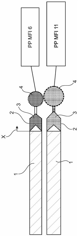
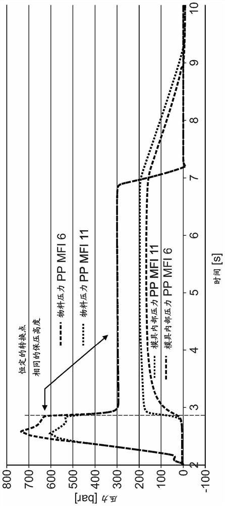
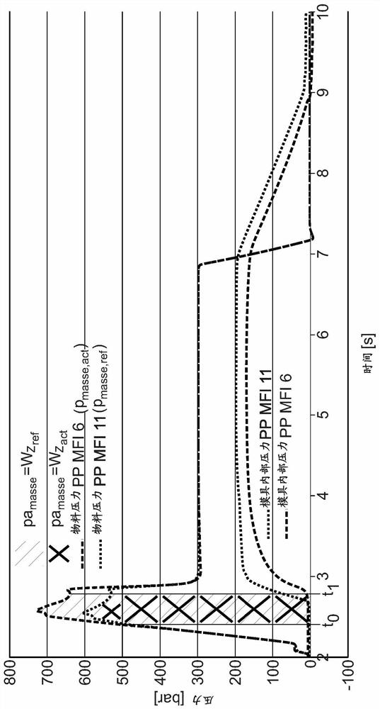
[0157] Now, next, with the help of figure 1 and figure 2 To illustrate the basic relationship between cavity pressure, viscosity and filling volume during injection molding.

[0158] exist figure 1 A worm 1 in a worm cylinder 2 of a plastic injection molding machine (not shown) is strongly schematically shown in FIG. exist figure 1 In the upper illustration of , a polypropylene material (PP material) with a melt flow index (melt flow index, MFI) of 6 is provided in the worm antechamber 3 and, schematically, in the cavity 4 . This is a relatively high viscosity (viscous) material in the melt state. exist figure 1 In the example shown below, polypropylene is also present in the worm antechamber 3 and cavity 4, but this polypropylene is less viscous (thin) in the melt and has a melt flow index value of 11 MFI. It is clear that, in the same worm position X, cavity 4 contains more melt volume (fill volume) in the case of polypropylene with MFI=11. In the case of high-vi...


PUM


Abstract

The invention relates to a method for operating an injection-molding machine, the method comprising the steps: a) in a current injection-molding cycle, after an accepted-part reference injection-molding cycle learned in a learning phase: detecting a compound pressure change k1 relative to an accepted-part reference compound pressure pmasse,ref during at least part of an injection phase of the current injection-molding cycle by measuring a current compound pressure pmasse,act and comparing the current compound pressure pmasse,act with the accepted-part reference compound pressure pmasse,ref; b) determining a target mold internal pressure curve pwkz,soll(t) for a holding-pressure phase of the current injection-molding cycle, wherein for this purpose a mold internal pressure curve pwkz,ref (t) of the accepted-part reference injection-molding cycle is adjusted at least in dependence on the compound pressure change k1 detected in step a); and c) traveling the holding-pressure curve pmasse,Hld,act(t) of the current injection-molding cycle in such a way that an actual mold internal pressure curve pwkz,act(t) of the current injection-molding cycle runs at least more closely along the target mold internal pressure curve pwkz,soll(t) than a mold internal pressure curve pwkz,ref(t) that is unchanged in comparison with the accepted-part reference cycle.

Description

technical field [0001] The invention relates to a method according to the preamble of claim 1 for operating an injection molding machine, in particular with regard to improved mold filling, and an injection molding machine for carrying out the method. Background technique [0002] Conventional injection molding machines comprise, inter alia, an injection molding tool into which molten plastic mass is introduced. In this case, there are one or more cavities in the injection molding tool, which are cavity spaces for the components. The mold also includes a distribution system through which the molten plastic mass enters the cavity(s). Injection molding machines generally comprise heated cylinders by means of which the injection molding compound is melted and injected into the injection molding tool. A worm for advancing injection molding material is provided in the cylinder. Conventional injection molding machines usually also include a fully adjustable drive for the worm, ...

Claims


Application Information

Patent Timeline
Patent Type & Authority Applications(China)
IPC IPC(8): B29C45/77B29C45/76
CPCB29C45/77B29C45/766B29C2945/76006B29C2945/76257B29C2945/76969B29C2945/76381B29C2945/76404B29C2945/76384B29C2045/776B29C45/7646B29C2945/76197B29C45/762B29C2945/76949B29C2945/76498B29C2945/76882
Inventor S·莫泽N·托皮克S·格雷格
Owner KRAUSSMAFFEI TECH GMBH
Why Eureka
Try Eureka