Multi-beam p-time root compression coherence filtering beam forming method and device

A beam forming device and beam forming technology are applied in ultrasonic/sonic/infrasonic diagnosis, ultrasonic/sonic/infrasonic image/data processing, sound wave diagnosis, etc., and can solve frame rate, penetration, lateral resolution and space Problems such as incompatibility of contrast

Pending Publication Date: 2021-06-04
深圳蓝影医学科技股份有限公司
View PDF6 Cites 1 Cited by
  • Summary
  • Abstract
  • Description
  • Claims
  • Application Information

AI Technical Summary

Problems solved by technology

[0013] The above related patents all have the problem that frame rate, penetrating power, horizontal resolution and spatial contrast cannot be achieved at the same time

Method used


Image

  • Multi-beam p-time root compression coherence filtering beam forming method and device
  • Multi-beam p-time root compression coherence filtering beam forming method and device
  • Multi-beam p-time root compression coherence filtering beam forming method and device

Examples


preparation example Construction

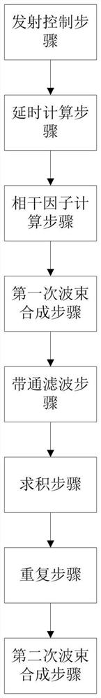
[0044] Please refer to figure 1 , the multi-beam p-order root compressed coherent filter beamforming method of the embodiment of the present invention includes a transmission control step, a delay calculation step, a coherence factor calculation step, a first beamforming step, a bandpass filtering step, a quadrature step, and a repeating step and the second beamforming step.

[0045] In the embodiment of the present invention, the signals received by each channel are subjected to P times of root sign compression, and then accumulated and summed. The multi-beam p-root compressive coherent filter beamforming proposed in this paper refers to the fact that in the process of multi-beam receiving beamforming, the first beamforming performs p-root compressive nonlinear beamforming, and the result is band-pass filtered to remove Noisy signal caused by nonlinear operation.

[0046] Adaptive weighted imaging technology can perform dynamic weighting according to the characteristics of ...

Embodiment approach

[0050] As an implementation, the calculation formula is as follows

[0051]

[0052] where S(k) is s n The frequency domain expression of (t), S(k)=FFT(s n (t)), k is frequency, unit (Hz), range 10 Adjust parameters for low-frequency components, via M 0 The low-frequency signal energy of GCF can be adjusted, which can be set according to the system situation. Generally, M 0 ≤3 to ensure better background intensity.

[0053] When taking M 0 = 0, take the DC component, GCF degenerates into CF, and the calculation formula of CF is as follows.

[0054]

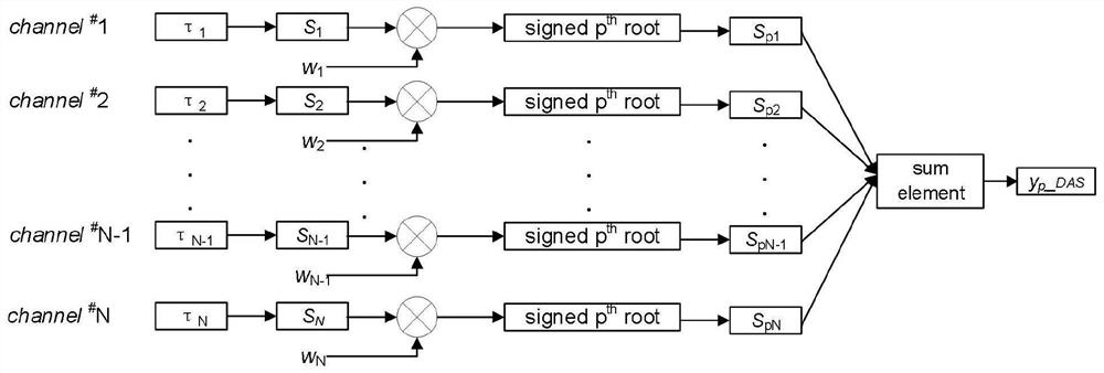
[0055] The first beamforming step: for the data s of each channel (single channel) of the multi-beam n (t) multiplied by Hanning window apodization coefficient w n , and then perform p root compression beamforming operations to obtain the compression and accumulation sum result y of each channel p _DAS(t), and then get the first beamforming signal y p _DAS.

[0056] As an implementation, the calculation formula is a...


PUM


Abstract

The embodiment of the invention discloses a multi-beam p-time root compression coherence filtering beam forming method and device. The method comprises the following steps: performing transmission control, namely transmitting ultrasonic waves once in a fixed-point focusing manner; performing delay calculation, namely performing dynamic focusing, multi-beam receiving and delay calculation to obtain data of each channel of multiple beams; performing coherence factor calculation, namely calculating a generalized coherence factor of each wave beam in sequence; performing first-time beam forming, namely performing p-time root signal compression beam forming operation to obtain a first-time beam forming signal; performing band-pass filtering, namely carrying out band-pass filtering; performing quadrature, namely weighting coherence factors; repeating the steps, namely repeating the emission control step to the quadrature step to obtain a multi-beam signal required by a frame of image; and performing second-time beam forming, namely carrying out second-time apodization, and then carrying out coherent superposition on multiple beams to obtain a second-time beam forming signal. According to the method, the beam forming quality is effectively improved, and the contrast resolution, the spatial resolution and the frame rate of the image are further improved.

Description

technical field [0001] The invention relates to the technical field of ultrasonic imaging, in particular to a multi-beam p-order root compression coherent filter beam synthesis method and device. Background technique [0002] Ultrasound imaging is widely used in clinical medical diagnosis because of its advantages of safety, real-time, portability, non-invasiveness and low cost. [0003] Ultrasound imaging image quality is related to contrast resolution, spatial resolution, frame rate, etc., traditional DelayAnd Sum (DAS) beamforming, the beam formed by it has a higher side lobe and a wider main lobe; Although the traditional apodization technology can reduce the side lobe, it increases the width of the main lobe and reduces the spatial resolution of the image. Although the traditional technology is simple and easy to implement, it does not effectively improve the image quality. [0004] The weighting factor is usually a coefficient constructed by using the coherence of th...

Claims


Application Information

Patent Timeline
Patent Type & Authority Applications(China)
IPC IPC(8): A61B8/00
CPCA61B8/52A61B8/5215
Inventor 龙丽孙瑞超陈晶丁浩
Owner 深圳蓝影医学科技股份有限公司
Why Eureka
Try Eureka