Tomography-Based and MRI-Based Imaging Systems

a technology of imaging system and tomography, applied in the field of medical imaging, can solve the problems of image artifacts in existing interior tomography reconstruction algorithms, drop in image intensity, etc., and achieve the effects of improving temporal, spatial and contrast resolution, reducing examination time, and improving image quality

Inactive Publication Date: 2011-06-16
WANG GE +5
View PDF0 Cites 222 Cited by
  • Summary
  • Abstract
  • Description
  • Claims
  • Application Information

AI Technical Summary

Benefits of technology

[0028]The inventive method of projection onto convex sets based interior-tomography reconstruction algorithm is an improved method over existing systems. The exemplary algorithm described herein can provide comparable image quality even in the absence of known sub-region and using only one filtering direction. These methods were applied to real projection data thus demonstrating the suitability of our methods for practical applications.
[0029]Objects of embodiments of the invention further provide for interior MR imaging of the heart with significantly improved temporal, spatial and contrast resolution. One solution is to provide interior MR imaging of the heart in the compressed sensing framework. Specifically, embodiments of the invention involve combining a newly developed 3D radial MRI method (called UTE-GRE)[2-3], compressed sensing techniques [4-5], and interior tomography principles [6-7]. Using 2D radial MR data acquisition with the aid of a digital filter, a ROI-focused MR image of a phantom has already been successfully reconstructed using the interior tomography approach by our team [8], and can be enhanced using 3D radial data acquisition and the compressed sensing approach described in this disclosure. It is expected that interior MRI of the heart will decrease examination time and increase spatial resolution by at least a factor of 2 or more, and with enhanced contrast resolution to describe the deformation of the myocardium, compared to the state-of-the-art 2D multi-slice techniques for cine MRI such as radial k-t FOCUSS[9]E. Such an improvement is significant for extraction of cardiac elastodynamic biomarkers as well as for the clinical applications of cardiac MRI.
[0030]The present invention further provides a tomography-based nonlinear dynamic cardiac elastography (DCE) framework for characterization of the mechanical properties of myocardium based on blood pressure and heart deformation measured with biomedical imaging techniques. The nonlinear DCE estimates the mechanical parameters by optimally minimizing the difference between computed dynamic epi- and endocardial displacement and the corresponding experimental measurement. A dynamic nonlinear adjoint method can be used to calculate the gradients of the objective function. Investigated. The nonlinear DCE may prove indispensable for identification of the viscoelastic properties of myocardium.
[0031]Additionally, both temporal and spatial resolution can be significantly improved using a region of interest (ROI)-focused MRI data acquisition scheme. In many practical MRI applications, i.e., cardiac imaging, only a small portion of the field of view (FOV) may be of clinical interest. To image a ROI may still provide sufficient clinical information. However, in radial MRI, there is no such an acquisition-based solution available. The present invention provides an interior MRI methodology to perform ROI reconstruction without artifacts, or with a reduced amount of artifacts.

Problems solved by technology

Existing interior tomography reconstruction algorithms suffer from image artifacts like a drop in image intensity.

Method used


Image

  • Tomography-Based and MRI-Based Imaging Systems
  • Tomography-Based and MRI-Based Imaging Systems
  • Tomography-Based and MRI-Based Imaging Systems

Examples


Embodiment Construction

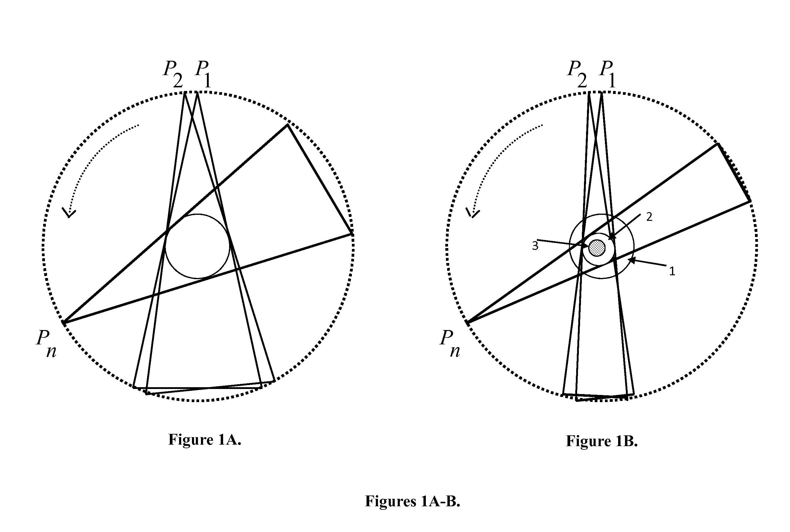
. Ultra-Fast Tomography. For a general CT-scan of the heart and the coronary arteries, a field of view (FOV) of ˜15 cm in diameter is preferred (apart from some very special cases where e.g. only the middle part of the right coronary artery would be of interest) and can be achieved using multi-source interior tomography by utilizing a limited number of sources to increase the ROI coverage and scanning the source-detector chains in a circular, saddle-curve or another trajectory to avoid under-sampling, cross-scattering, and other issues. In the case of 2N+1 sources, the radius r of the field of view (FOV) can be maximized by arranging the source-detector pairs equi-angularly to reach:

r=Rsin(π4N+2),(3)

[0438]where R is the radius of the scanning circle.

[0439]According to Eq. (3), the radius of FOV is decreased as the number of sources is increased. Specifically, we can cover an FOV of 16.2 cm or 13.4 cm in diameter with 11-source or 13-source interior tomography architectures respectiv...


PUM


Abstract

Tomography limitations in vivo due to incomplete, inconsistent and intricate measurements require solution of inverse problems. The new strategies disclosed in this application are capable of providing faster data acquisition, higher image quality, lower radiation dose, greater flexibility, and lower system cost. Such benefits can be used to advance research in cardiovascular diseases, regenerative medicine, inflammation, and nanotechnology. The present invention relates to the field of medical imaging. More particularly, embodiments of the invention relate to methods, systems, and devices for imaging, including tomography-based and MRI-based applications. For example, included in embodiments of the invention are compressive sampling based tomosynthesis methods, which have great potential to reduce the overall x-ray radiation dose for a patient. To name a few, compressive sensing based carbon nano-tube based interior tomosynthesis systems, tomography-based dynamic cardiac elastography systems, cardiac elastodynamic biomarkers from interior MR imaging, exact and stable interior ROI reconstructions for radial MRI, and interior reconstruction based ultrafast tomography systems are provided.

Description

CROSS-REFERENCE TO RELATED APPLICATIONS[0001]This application relies on the disclosure of and claims the benefit of the filing date of U.S. Provisional Application Nos. 61 / 256,099, filed Oct. 29, 2009; 61 / 260,242, filed Nov. 11, 2009; and 61 / 260,577, filed Nov. 12, 2009; the disclosures of each of which are incorporated by reference herein in their entireties.STATEMENT OF GOVERNMENT INTEREST[0002]This work was partially supported by the National Institutes of Health under NIH / NIBIB Grants RO1HL098912, EB011785, EB002667, EB004287 and EB00728A; NIH / NHLBI Grant HL098912; NSF Grant DMS0811254; and NIH / NCI Grant CA135151. The U.S. Government has certain rights in this invention.BACKGROUND OF THE INVENTION[0003]1. Field of the Invention[0004]The present invention relates to the field of medical imaging. More particularly, embodiments of the invention relate to methods, systems, and devices for imaging, including tomography-based and MRI-based applications.[0005]2. Description of the Rela...

Claims


Application Information

Patent Timeline
Patent Type & Authority Applications(United States)
IPC IPC(8): G06K9/00
CPCG06T11/006G06T2211/432G06T2211/424
Inventor WANG, GEYU, HENGYONGZHOU, OTTOCAO, GUOHUORITMAN, ERIKVANNIER, MICHAEL
Owner WANG GE
Why Eureka
Try Eureka