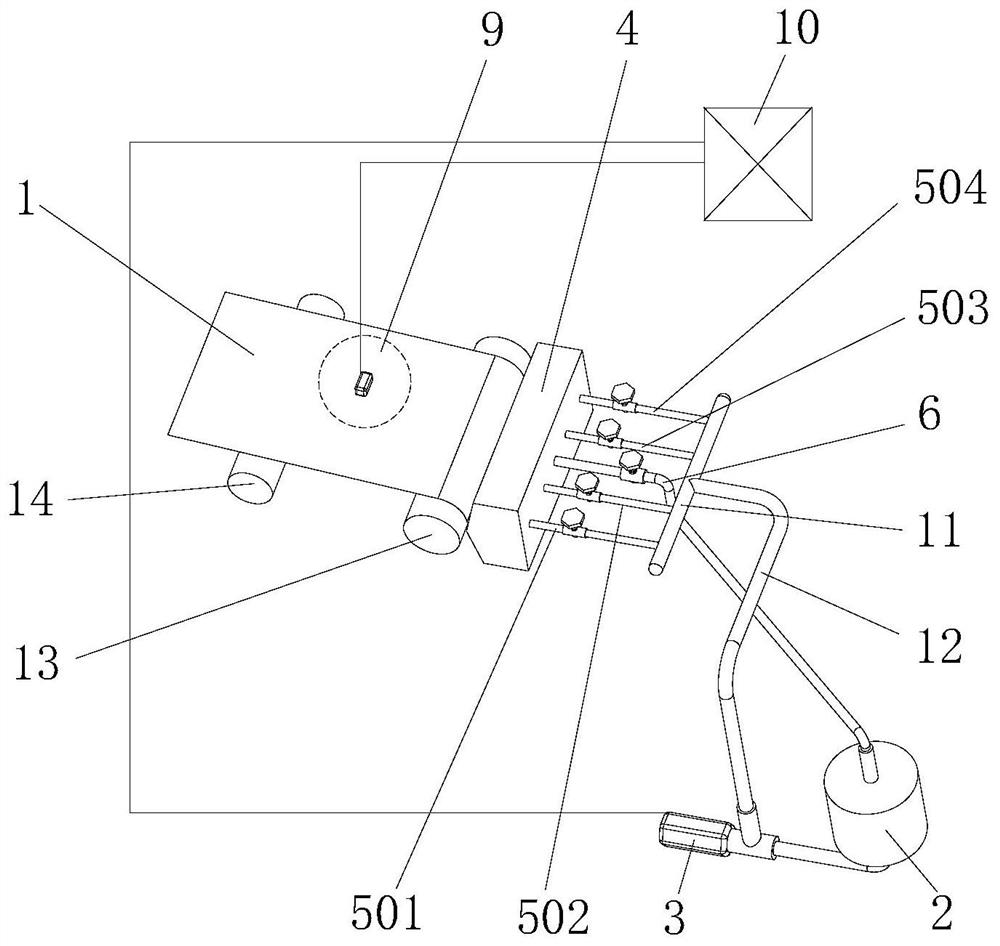
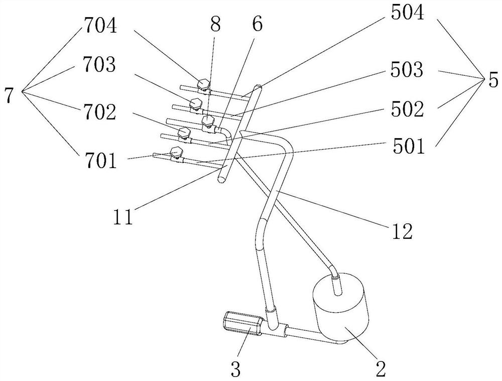
Foil coating device

A technology of coating device and foil material, which is applied in the direction of surface coating liquid device and coating, etc., which can solve the problems of bad interface of battery pole pieces, poor adjustment efficiency and effect, safety accidents, etc.

Active Publication Date: 2021-06-04
SVOLT ENERGY TECHNOLOGY CO LTD
View PDF9 Cites 3 Cited by
  • Summary
  • Abstract
  • Description
  • Claims
  • Application Information

AI Technical Summary

Problems solved by technology

Among them, the uniformity of the coating surface density of the foil is a key indicator of the coating quality. It is very important to improve the electrical performance and ensure the safety of the battery. Not up to the standard; if the negative electrode coating surface density consistency is poor, it will lead to poor battery electrode interface, which will lead to safety accidents
[0004] Based on the current lithium battery production process, when the foil coating process is performed, the viscosity of the slurry will change with time, such as agglomeration, or sometimes due to the poor filtering effect of the filtration system. Good, resulting in poor slurry fluidity and affecting coating quality
In particular, as the width of the foil corresponding to the coating becomes larger and larger, it is more difficult to ensure the consistency of the surface density of the foil coating
However, the existing coating device mainly adjusts the coating surface density by adjusting the screw of the die head, adjusting the pump speed of the feeding pump or adjusting the feeding and retreating of the die head. It is difficult to solve the above problems well, and online adjustment cannot be realized. Partial coating area density, regulation efficiency and poor regulation effect

Method used


Image

  • Foil coating device
  • Foil coating device
  • Foil coating device

Examples


Embodiment Construction

[0041] It should be noted that, in the case of no conflict, the embodiments of the present invention and the features in the embodiments can be combined with each other.

[0042] In the description of the present invention, it should be noted that if there are terms indicating orientation or positional relationship such as "upper", "lower", "inner" and "back", it is based on the orientation or positional relationship shown in the drawings , is only for the convenience of describing the present invention and simplifying the description, but does not indicate or imply that the referred device or element must have a specific orientation, be constructed and operated in a specific orientation, and thus should not be construed as limiting the present invention. In addition, if terms such as "first" and "second" appear, they are used for descriptive purposes only, and cannot be understood as indicating or implying relative importance.

[0043]In addition, in the description of the pr...


PUM

PropertyMeasurementUnit
widthaaaaaaaaaa
thicknessaaaaaaaaaa
thicknessaaaaaaaaaa

Abstract

The invention provides a foil coating device which is used for coating conveyed foil and structurally comprises a feeding mechanism, a coating die head mechanism, a surface density detection mechanism and a control mechanism on the whole. The feeding mechanism is provided with a slurry storage unit and a pumping unit which is connected with the slurry storage unit and used for pumping slurry. The coating die head mechanism is provided with a coating die head, feeding pipes and a return pipe, the feeding pipes are connected with the pumping unit, the return pipe is connected with the slurry storage unit, the plurality of feeding pipes are arranged at intervals and are respectively connected with regulating valves in series, and a coating opening of the coating die head is divided into a plurality of sections which are in one-to-one correspondence with the feeding pipes. The surface density detection mechanism is arranged corresponding to the foil so as to collect the surface density of the foil after coating. The control mechanism is connected with the surface density detection mechanism, the pumping unit and each regulating valve. According to the foil coating device, the density of a coating surface can be adjusted on line, the coating operation efficiency is effectively improved, and the practicability of the device is high.

Description

technical field [0001] The invention relates to the technical field of foil coating equipment, in particular to a foil coating device. Background technique [0002] With the in-depth implementation of the national sustainable development strategy, lithium batteries, as a more prominent member of the new energy industry, have received more and more attention from all walks of life, and have been applied to people's daily life, especially digital products, Automobile and other electric tools and other industries. [0003] Coating is an important process in the production process of lithium batteries. Generally speaking, it is to uniformly coat the active material on the current collector (copper foil / aluminum foil) according to a certain weight. The coated current collector (also can be It is called pole piece or foil) and can be used in the next process. Among them, the uniformity of the coating surface density of the foil is a key indicator of the coating quality. It is ve...

Claims


Application Information

Patent Timeline
Patent Type & Authority Applications(China)
IPC IPC(8): B05C5/00B05C11/10B05C13/02
CPCB05C5/00B05C11/1002B05C11/1039B05C13/02
Inventor 马毅丁亚男苏夏
Owner SVOLT ENERGY TECHNOLOGY CO LTD
Why Eureka
Try Eureka