Metal powder screening device for 3D printing

A metal powder and screening device technology, applied in the field of 3D printing, can solve the problems of affecting the screening speed, the inability to adjust the screen freely, and the blockage of the screen

Inactive Publication Date: 2021-06-04
JIANGSU VILORY ADVANCED MATERIALS TECH CO LTD
View PDF12 Cites 4 Cited by
  • Summary
  • Abstract
  • Description
  • Claims
  • Application Information

AI Technical Summary

Problems solved by technology

[0003] However, there are some deficiencies in the current screening device. When screening, the metal powder is usually poured directly into the screen for sand screening. Pouring too much metal powder at one time will not only affect the screening speed, but also cause the screen to break. Blockage, pouring too little metal powder will affect the progress of the work. At the same time, the existing screening device cannot freely adjust the aperture of the screen according to the demand, and the flexibility is poor

Method used


Image

  • Metal powder screening device for 3D printing
  • Metal powder screening device for 3D printing
  • Metal powder screening device for 3D printing

Examples


Embodiment 1

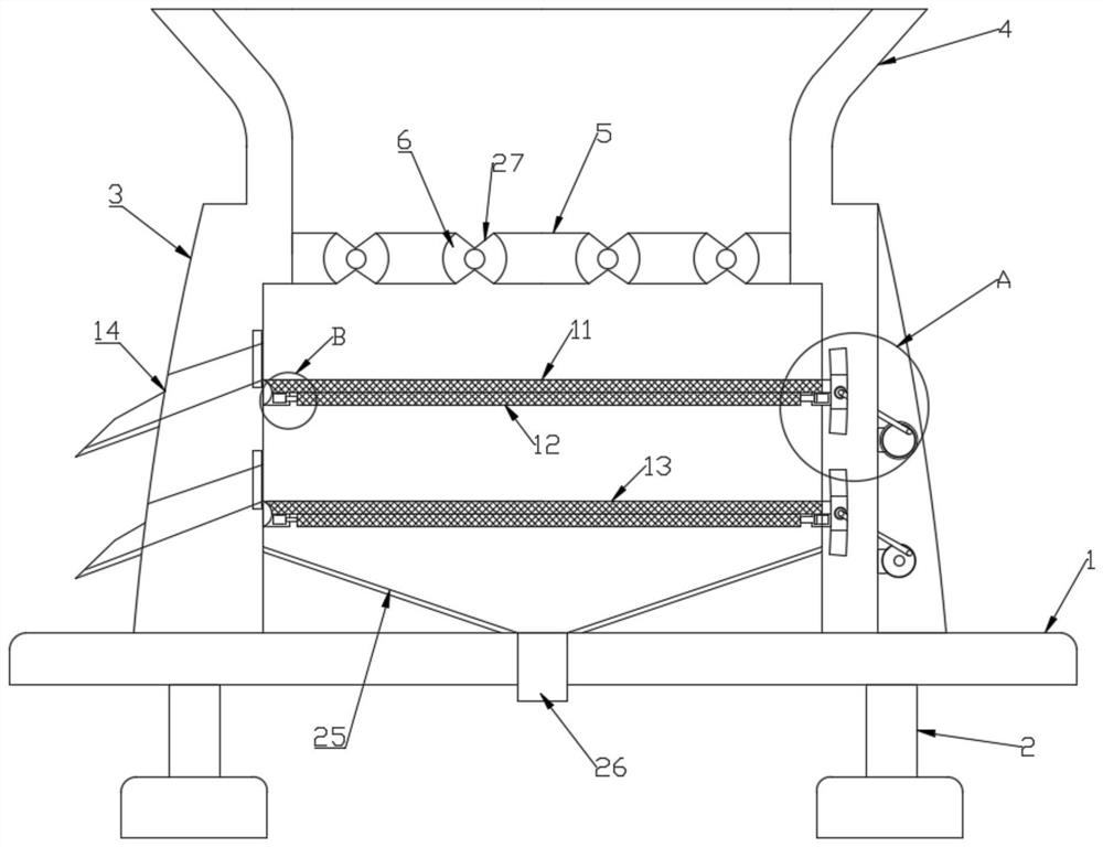
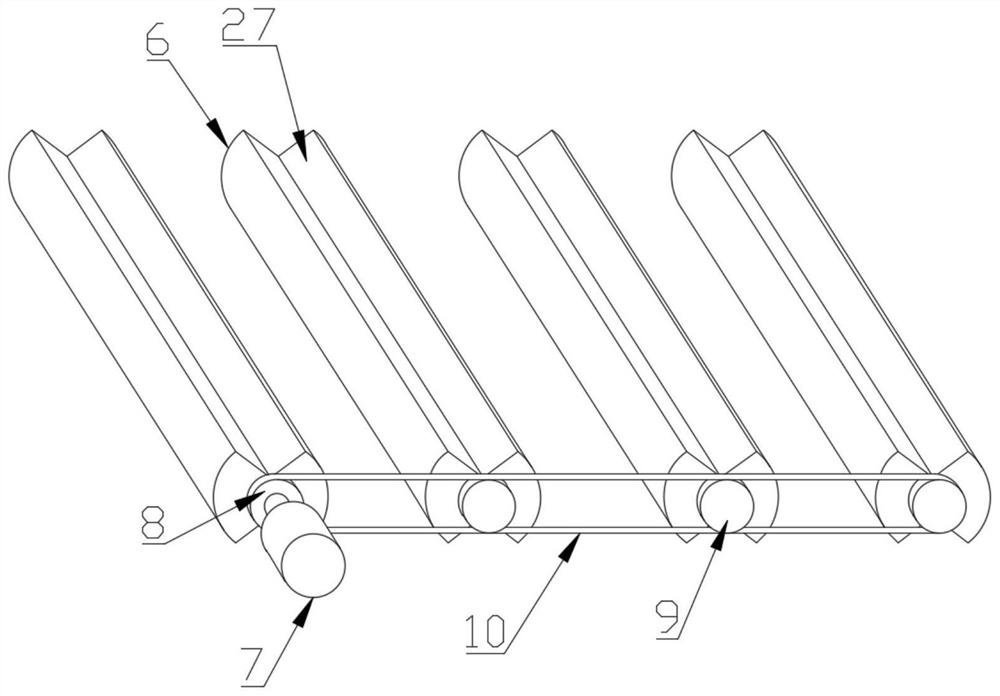
[0025] see Figure 1-4 , this embodiment provides a metal powder screening device for 3D printing, including a base 1, a support foot 2 and a housing 3, the support foot 2 is fixedly installed on the bottom of the base 1, and the upper end of the base 1 is fixedly installed There is a housing 3, the upper end of the housing 3 is provided with a feed inlet 4, and a partition plate 5 is fixedly installed in the housing 3, and the partition plate 5 divides the housing 3 into two parts. A quantitative addition mechanism is installed on the partition plate 5, and a screening mechanism is installed inside the housing 3 below the partition plate 5;

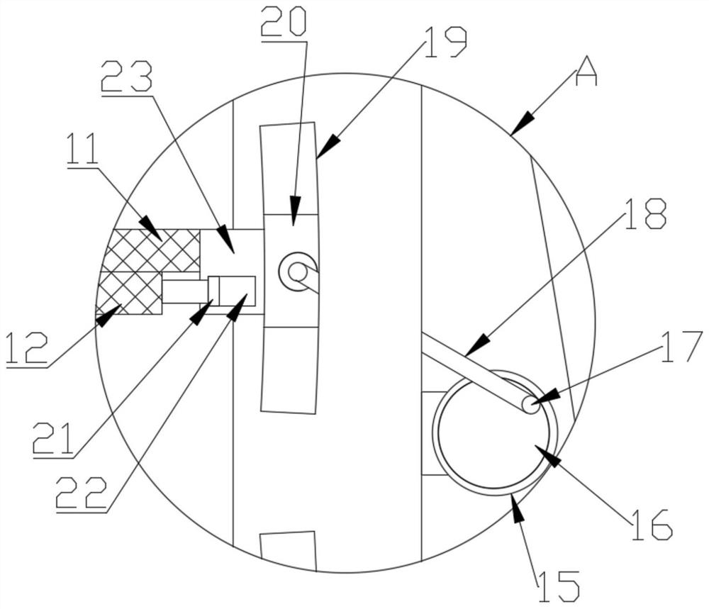
[0026] The screening mechanism is composed of two screening assemblies with the same structure, and the two screening assemblies are arranged up and down sequentially, and one screening assembly includes a screen frame 23, a No. 2 motor 15, a rotating disk 16, a connecting Rod 17 and slide block 20, one end of described screen frame 23 ...

Embodiment 2

[0039] In order to avoid metal powder remaining on the No. 2 discharge port 14 and the guide plate 25, this embodiment is further improved on the basis of Embodiment 1. The improvement is that the inner wall of the No. 2 discharge port 14 and the guide plate 25 The upper ends of both are polished. This setting can reduce the resistance received by the metal powder when it moves, thereby avoiding the phenomenon of metal powder residue.

[0040] The last few points should be explained: First, in the description of this application, it should be explained that, unless otherwise specified and limited, the terms "installation", "connection" and "connection" should be understood in a broad sense, which can be mechanical connection Or electrical connection, it can also be the internal communication of two parts, it can be directly connected, "up", "down", "left", "right" and so on are only used to indicate the relative positional relationship, when the absolute position of the object ...


PUM


Abstract

The invention discloses a metal powder screening device for 3D printing. The metal powder screening device comprises a base, supporting legs and a shell, the supporting legs are fixedly installed at the bottom of the base, the shell is fixedly installed at the upper end of the base, a feeding port is formed in the upper end of the shell, a partition plate is fixedly installed in the shell, and the interior of the shell is divided into two parts by the partition plate; and a quantitative adding mechanism is installed on the partition plate, and a screening mechanism is installed below the partition plate inside the shell. When the metal powder screening device is used, two screening assemblies on the screening mechanism can conduct screening on metal powder twice, due to the fact that the hole diameters of screens on the two screening assemblies are different, the metal powder can be divided into three parts according to different particle sizes, meanwhile, adjusting mechanisms installed on screen frames can adjust the hole diameters of the screens, and therefore the maximum hole diameter of the screened metal powder can be freely controlled according to requirements.

Description

technical field [0001] The invention relates to the technical field of 3D printing, in particular to a metal powder screening device for 3D printing. Background technique [0002] Metal powder is the raw material for 3D printing, and the particle size distribution is usually in the range of 15-53 μm. At present, the particle size of powder obtained by various atomization methods is in the range of 0-300 μm. Therefore, in order to obtain metal powder for 3D printing, it is necessary to The atomized powder with a wide particle size range is sieved. [0003] However, there are some deficiencies in the current screening device. When screening, the metal powder is usually poured directly into the screen for sand screening. Pouring too much metal powder at one time will not only affect the screening speed, but also cause the screen to break. Blocking, pouring too little metal powder will affect the progress of the work. At the same time, the existing screening device cannot freel...

Claims


Application Information

Patent Timeline
Patent Type & Authority Applications(China)
IPC IPC(8): B07B1/30B07B1/42B07B1/46B22F1/00B33Y40/10
CPCB07B1/30B07B1/42B07B1/4636B07B1/46B33Y40/10B07B2201/04B22F1/14
Inventor 张维蒋保林许荣玉叶国晨张柯唐跃跃魏放武加全
Owner JIANGSU VILORY ADVANCED MATERIALS TECH CO LTD
Why Eureka
Try Eureka