
Rotary mechanism for automatic testing of computer devices

An automatic detection and slewing mechanism technology, which is applied in the direction of instruments, measuring devices, and optical devices, can solve problems such as detecting gaps, and achieve the effects of saving costs, shortening no-load time, and saving work space

Active Publication Date: 2022-07-12
WUHAN PANSHENG DINGCHENG TECH CO LTD
View PDF5 Cites 0 Cited by
  • Summary
  • Abstract
  • Description
  • Claims
  • Application Information

AI Technical Summary

Problems solved by technology

[0004] In order to overcome the problem of gap detection in the existing linear assembly line detection equipment, the present invention provides a rotary mechanism for automatic detection that can automatically perform various detections on computer devices. Through two rotating rotary mechanisms, the conveyor belt assembly line The hard disk on the top is removed and placed on the first rotary mechanism, and it is detected by four detection stations in sequence, and when it is detected as unqualified, the material transport mechanism of the outer ring is lowered by switching the speed of the first turntable and the second turntable. material and speed up the rotation to the loading position, improving the efficiency of the station

Method used


Image

  • Rotary mechanism for automatic testing of computer devices
  • Rotary mechanism for automatic testing of computer devices
  • Rotary mechanism for automatic testing of computer devices

Examples


Embodiment 1

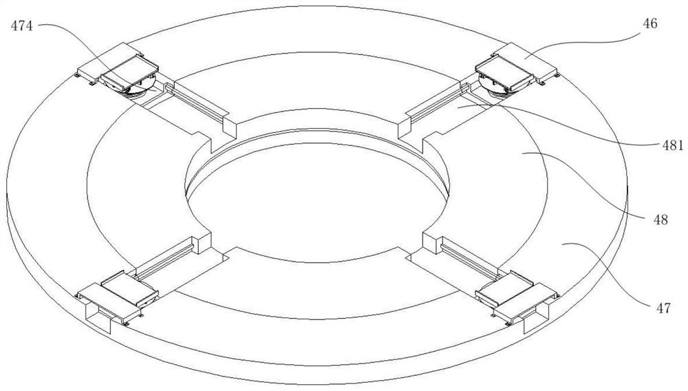
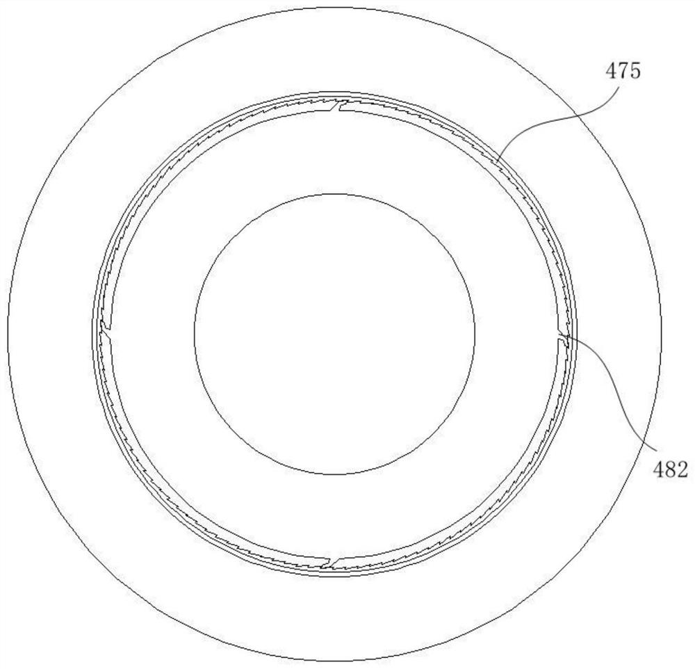
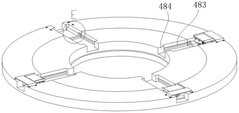
[0038] like Figures 1 to 8 As shown, a rotary mechanism for automatic detection of computer devices includes a first rotary mechanism 4 and a second rotary mechanism 5 arranged horizontally, and the first rotary mechanism 4 and the second rotary mechanism 5 are in the direction along the conveyor belt assembly 2. When connected, the transfer of the computer device to be detected can be realized. The first rotary mechanism 4 includes a first rotary table 47 and a second rotary table 48 that are rotatably connected, a number of material transport mechanisms 46 that can move back and forth along the end face of the rotary mechanism, and are arranged on The second push-pull mechanism in the middle of the first rotary mechanism 4, the first turntable 47 and the second turntable 48 can be driven by the second turntable 48 to rotate the first turntable 47 synchronously, or the first turntable 47 can be accelerated Rotating and the rotation speed of the second turntable 48 is constan...

Embodiment 2

[0050] like Figures 1 to 14 As shown, this embodiment specifically applies the rotary mechanism of Embodiment 1 to the detection of computer hard disks, and forms a computer hard disk batch detection equipment, which is provided with a conveyor belt assembly 2 in addition to the rotary mechanism in Embodiment 1. 2. The first push-pull mechanism 3 is arranged on one side of the conveyor belt assembly 2, and the first rotation mechanism 4 is arranged on the other side of the conveyor belt assembly 2 relative to the first push-pull mechanism 3, and the second rotation mechanism 5 is arranged on the first push-pull mechanism 3. A rotary mechanism 4 is in the direction of the conveyor belt assembly 2, and the first rotary mechanism 4 and the second rotary mechanism 5 are connected in the direction of the conveyor belt assembly 2, which can realize the transfer of the hard disk to be tested.

[0051] In this embodiment, the first push-pull mechanism 3 is fixed to one side of the co...


PUM


Abstract

The invention discloses a rotary mechanism for automatic detection of computer devices, comprising a first rotary mechanism and a second rotary mechanism arranged horizontally; the first rotary mechanism comprises a first rotary table and a second rotary table that are rotatably connected, and several rotary The material conveying mechanism with the end face of the mechanism moving back and forth, the second push-pull mechanism arranged in the middle of the first rotating mechanism, the first rotating mechanism is sequentially provided with several detection stations and a material moving station; the second rotating mechanism is on the Several detection mechanisms are provided, and the several detection mechanisms are respectively connected with detection boxes arranged on the upper end of the second rotation mechanism. Different types of detection mechanisms can be provided on the first rotation mechanism and the second rotation mechanism. Through the above method, the rotary mechanism for automatic detection of computer devices of the present invention can automatically perform various detections on computer devices by configuring different detection mechanisms, with high detection efficiency and no waste of workstations.

Description

technical field [0001] The invention relates to the field of automatic detection, in particular to a rotary mechanism for automatic detection of computer devices. Background technique [0002] With the increasing popularity of computers, the scale of its production is also increasing. There are many devices involved in the computer, and there are high standards for the quantity and quality of its production. In industrial production, the detection of the components in the computer usually requires the following aspects to be tested, including appearance inspection, load For force detection and its performance detection, although devices for automatic detection of devices have been developed on the market, most of them adopt the design method of linear assembly line. This detection method is to detect devices one by one and one by one. When the object is initially found to have defects and is rejected, there is a problem of detection gaps, which makes the detection equipment...

Claims


Application Information

Patent Timeline
Patent Type & Authority Patents(China)
IPC IPC(8): B07C5/00B07C5/344B07C5/02B07C5/36B07C5/38G01B21/20G01B11/00
CPCB07C5/00B07C5/344B07C5/02B07C5/362B07C5/38G01B21/20G01B11/00
Inventor 王颖学唐小景
Owner WUHAN PANSHENG DINGCHENG TECH CO LTD
Learn More