
Dotting machine

A dotting machine and machine body technology, applied in metal processing equipment, feeding devices, manufacturing tools, etc., can solve the problems of low production efficiency and achieve the effect of improving processing efficiency and continuous supply efficiency

Active Publication Date: 2021-06-04
余姚市恒辉仪表有限公司
View PDF6 Cites 0 Cited by
  • Summary
  • Abstract
  • Description
  • Claims
  • Application Information

AI Technical Summary

Problems solved by technology

[0004] In view of the above-mentioned related technologies, the inventor believes that the ordinary method of dotting the watch case can only make one snap-in convex point or snap-in concave point on the watch case each time, and the production process needs to repeat the dotting operation many times to achieve the desired result. effect, so there is a defect of low production efficiency

Method used


Image

  • Dotting machine
  • Dotting machine
  • Dotting machine

Examples


Embodiment Construction

[0039] The following is attached Figure 1-7 The application is described in further detail.

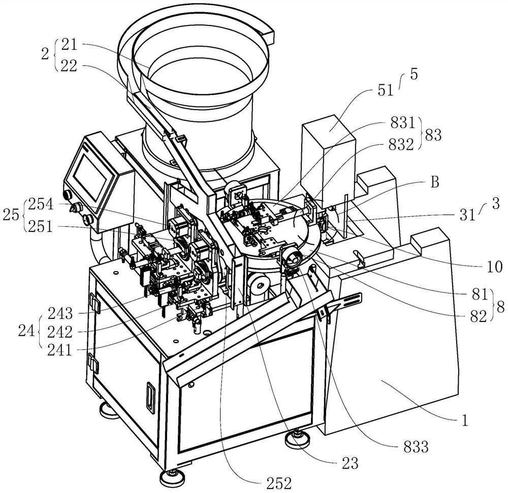
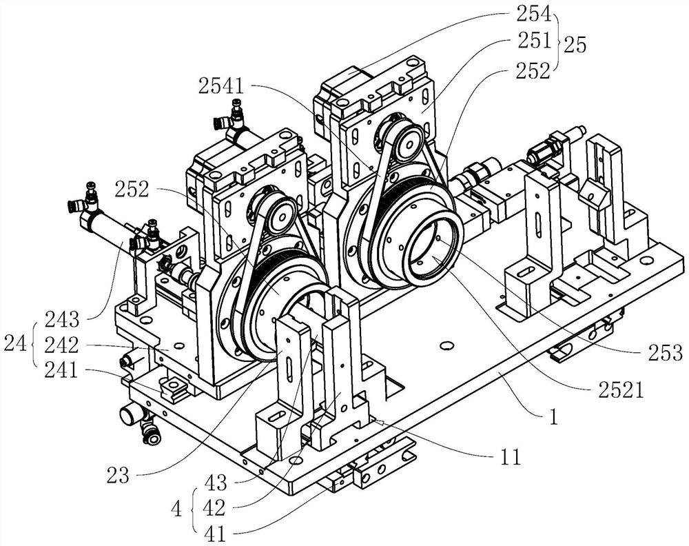
[0040] The embodiment of the present application discloses a dotting machine, referring to figure 1 , including a body 1, a feeding mechanism 2, and a dotting mechanism 3, and the body 1 is used as a supporting body for feeding the feeding mechanism 2, the dotting mechanism 3, and the like. The feeding mechanism 2 includes a vibrating plate 21, a blanking slideway 22, a receiving tray 23, a pushing assembly 24, and an adjustment assembly 25. The vibrating plate 21 is a spiral vibrating feeder 41, and its principle is to transfer the parts to the The edge of the disk body, and make the parts rotate under the action of the vibration wave, so as to realize the feeding process of the parts falling from the disk body one by one; It is inclined downward to form a slideway for the material to slide down on the vibrating plate 21.

[0041] The end of the blanking chute 22 away from the vi...


PUM


Abstract

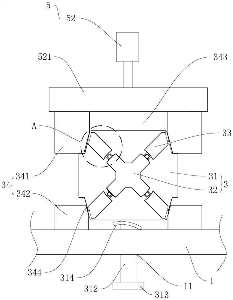
The invention relates to mechanical equipment, and discloses a dotting machine which particularly comprises a machine body, a feeding mechanism arranged on the machine body, and a dotting mechanism arranged on the machine body and used for dotting materials. The dotting mechanism comprises a locating plate arranged on the machine body and provided with a locating column, dotting heads slidably arranged on the locating plate and distributed around the locating column, and a driving assembly arranged on the machine body and used for driving the dotting heads to move towards the locating column, wherein a plurality of dotting protrusions distributed in the circumferential direction of the locating column are arranged on the side wall of the locating column; and dotting grooves for the dotting protrusions to embed are formed in the end faces, facing the locating column, of the dotting heads. According to the dotting machine, full-process automation of watchcase feeding, aligning, transport, machining and discharging can be achieved, a plurality of clamping protruding points can be formed through one-time action, and therefore the production efficiency of dotting operation of shell parts can be greatly improved.

Description

technical field [0001] The present application relates to the field of machining equipment, in particular to a dotting machine. Background technique [0002] A pressure gauge refers to an instrument that uses elastic elements as sensitive elements to measure and indicate pressure higher than the environment. Its application is extremely common, and it pervades almost all industrial processes and scientific research fields. It can be seen everywhere in heat pipe network, oil and gas transmission, water and gas supply system, vehicle maintenance and other fields. [0003] At present, for a pressure gauge, it generally includes a case, a cover, a glass panel and an internal pressure value conversion structure. The connection between the case and the cover is generally in the form of a thread or a block. In terms of connection form, dots need to be punched on the watch case to form snap-in convex points or snap-in concave points. In this industry, the common process of dotting...

Claims


Application Information

Patent Timeline
IPC IPC(8): B21D22/04B21D43/16B21D43/00B21D43/10
CPCB21D22/04B21D43/16B21D43/003B21D43/10B21D43/026
Inventor 励赛祥
Owner 余姚市恒辉仪表有限公司
Learn More